

A marine cable tray route is a chain of exposed surfaces, cut edges, fasteners, drainage paths and future repair points. This guide helps buyers define the coastal or offshore duty, shortlist EG, HDG, ZAM or stainless systems on the same basis, and ask

Treat the tray route as a corrosion and maintenance system, not a metal sample.
Marine Cable Tray Specification: Coatings, Fixings and Maintenance
-
Home>
-
Blog>
-
Technology>
Marine Cable Tray for Coastal and Offshore Projects: Coatings, Fixings and Maintenance
15
2026.11
Exposure defines the system
A marine cable tray is not approved by the word “stainless”. The route is only as durable as its cut edges, contact metals, drainage, inspectability and repair method.
Two routes can use the same tray family and still perform differently. One sits under a protected canopy, washed occasionally and inspected from a walkway. The other is open to wind-driven spray, holds salt in a recess and receives maintenance once a year. A supplier cannot resolve that difference from a catalogue title alone.
This guide turns the site description into a controlled specification. It covers the duty statement, chloride failure locations, material and finish shortlist, interface hardware, drainage, acceptance evidence and repair. The next action is a line-by-line RFQ, not a promise that one coating solves every marine exposure.
chloridecut edgecontact metalwater trapUVrepairability
Write the marine duty before selecting a material
The first useful document is a one-page duty statement. It records where the route runs, what reaches the surface, how often the surface is cleaned and what the buyer will do when the first damage appears. This is more useful than a generic request for “marine grade” because it gives each proposed material a condition to answer.
Separate direct spray from atmospheric salt. A sheltered service gallery may collect moist air and condensation without receiving regular spray. A quay or roof edge can receive both. A washdown bay adds water volume and possibly chemicals. Offshore exposure may combine all three with difficult access and expensive downtime.
Separate product from project duty. The tray family, fixed environment and acceptance evidence are three separate decisions.
Define the maintenance boundary too. A route that can be hosed from grade is not the same as one behind cable racks or under a cover. The supplier may manufacture the tray, but the project still owns cleaning, inspection and the decision to replace a damaged section.
ExposureSheltered, open coast, splash zone, washdown or offshore deck.
WettingRain, spray, condensation, process water and dry-down time.
CleaningFresh-water rinse, chemical wash or no planned cleaning.
AccessCan the route be inspected, opened, cleaned and repaired?
Decision rule: If those four inputs are not written down, the material discussion is still preliminary.
A useful marine duty note answers five questions
What touches the tray: airborne salt, direct spray, wash water, condensation, dust or a chemical? How long does the surface remain wet? Which parts can be cleaned without removing cable? What temperature range and movement does the route see? Which failure would stop the facility, and how quickly could it be repaired?
Those answers let the factory separate a product question from a project question. The product can be a perforated, ladder, trunking or wire-mesh system. The project question is whether that product has the correct metal, finish, cover, supports, fasteners and evidence for this route. Keeping the two layers apart prevents a catalogue code from being mistaken for an installed-system approval.
How chloride and moisture find the first failure point
Salt does not attack every square metre in the same way. It collects where the surface stays wet, where the air moves slowly and where a crevice holds deposits. The highest-risk points are usually a sheared edge, a punched hole, the underside of a cover, a fastener head, a splice overlap and the contact between dissimilar metals.
For coated steel, the barrier is physical. A scratch, porosity, an incompletely coated cut edge or mechanical damage opens a path to the steel. Zinc can still provide sacrificial protection if the coating system and exposure allow it, but the geometry still has to drain and the damaged area still has to be repaired.
Follow the defect path, not only the metal grade
For stainless steel, the protection is a passive film. Chlorides, low oxygen in a crevice and surface contamination can break that film locally. A brown stain is not automatically structural failure, but it is a signal to inspect the surrounding crevice, cleaning history and contact metals. Stainless-on-stainless threaded joints also require attention to galling.
The environmental framework matters here. ISO 12944-2 classifies atmospheric corrosivity for steel structures from C1 to C5. ISO 9223 gives a broader framework for classifying and estimating atmospheric corrosivity for metals. Neither document automatically approves a tray design; they help the project define the environment it is asking the supplier to address.
Edge
Shear and punch operations expose surfaces that the flat sample does not represent.
Crevice
Salt and moisture remain under overlaps, washers, covers and poorly drained recesses.
Contact
Mixed metals create a galvanic couple that can concentrate attack at the fixing.
Shortlist EG, HDG, ZAM and stainless on one basis
HULK Metal catalogue families identify Q mild steel, A aluminium, S4 stainless 304 and S6 stainless 316. Steel routes can use EG, HDG, ZAM or powder coating. These options differ in mechanism, not just appearance: electro-galvanizing provides a thin zinc layer, hot-dip galvanizing builds a thicker metallurgically bonded layer, ZAM combines zinc with aluminium and magnesium, and powder coating provides a barrier with colour.
The catalogue lists HDG classes H45, H65 and H85 at 45, 65 and 85 micrometres. The code guide also identifies Z80 and Z275 ZAM options. Those are product codes to specify and verify, not a universal ranking. The actual choice must still account for the route, forming, cut edges, fixing compatibility and the records required.
Translate the product code into an exposure route
EG should not be rejected only because the site is outdoors, and stainless should not be selected only because the site is near the sea. Start with the duty statement. If the route is genuinely protected and dry, a simpler finish may be rational. If salt remains on a horizontal surface, the maintenance and drainage details become as important as the coating name.
Stainless 304 and 316 are available material families, with 316 intended for more demanding corrosion conditions in the local catalogue. For a route with chloride deposits, the buyer should specify the grade, cleaning method, fastener system and mixed-metal boundaries. The companion guide Pre-galvanized, HDG, ZAM, Stainless or Aluminum gives the product-level distinction; this article owns the project-level route decision.
| Route | What protects the steel | First inspection point | Question for RFQ |
|---|---|---|---|
| EG | Thin zinc layer | Cut edge and damaged face | Which E40/E80/E275 class applies? |
| HDG | Thicker zinc-iron layer | Thickness, drainage and post-cut repair | H45, H65 or H85 on this product? |
| ZAM | Zinc-aluminium-magnesium layer | Cut edge, scratch and exposure route | Z80/Z275 or another approved build? |
| 304 / 316 | Passive stainless surface | Crevice, contamination and fastener contact | Grade, finish, cleaning and fixing method? |
Protected coastal building
Confirm condensation, salt ingress and cleaning before paying for a heavier marine system. The relevant failure may be a damp crevice, not direct spray.
Open quay or roof
Check slope, drainage, cover ventilation, wind-driven spray and the exact fixing package. A flat sample cannot show these interactions.
Washdown area
Include chemical compatibility, water volume, caps, seals, cleaning access and the method for repairing damage after maintenance.
Remote offshore access
Prioritise removable modules, spare hardware, inspection reach and evidence that the installed route can be checked without long downtime.
Specify the condition beside the product code
A code such as H45, H65, H85, Z80, Z275, S4 or S6 is useful only when the route condition sits beside it. The same product family can serve a protected corridor and an exposed quay, but the acceptance questions are not the same. The RFQ should therefore read as a pair: “this material and finish, for this exposure, verified by these records.”
- State the material family and stainless grade.
- State the finish route and catalogue class.
- State the exposure and maintenance assumption.
Fixings and interfaces can defeat the tray material
Acceptance often stops at the tray. Installation starts at the interfaces. A stainless tray on a galvanised support, a coated tray with a bare screw or an aluminium route touching steel without separation creates a new corrosion cell. The correct material for the tray is not evidence that the complete fixing is correct.
For stainless fasteners, galling can lock a thread before the installer reaches the intended clamp load. The work instruction must identify whether a compatible lubricant is permitted, how the fastener is run down and how the selected torque is controlled. Do not use a universal torque value without the bolt size, grade, lubrication and joint design.
Write the interface as a controlled assembly
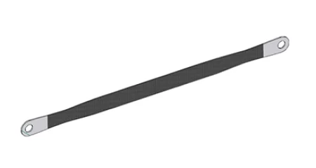
Electrical continuity is another system property. A conductive tray path may require a cleaned contact at the specified joint, a bonding conductor or a tested connection. Paint, powder coating, sealant and corrosion product can interrupt the intended path. The project drawing should show where continuity is required and how it is proven; the Cable Tray Bonding Jumper page covers one of those interface components.
Write the fixing schedule by interface: tray to support, tray to tray, cover to tray, support to structure and bonding connection. For each one, state the materials, washers, isolation, coating repair and acceptance. A “stainless hardware” note is not enough to control that list.
For the wider support, spacing and bonding sequence around this article, see Cable Tray Installation. The marine decision still remains separate: a generic installation detail does not prove that the selected material and fixing pair suit salt exposure.
| Interface | Main risk | Required record |
|---|---|---|
| Tray to support | Dissimilar-metal contact or trapped water | Fixing material, washer or isolator, coating repair |
| Tray to tray | Incomplete coupler kit or continuity | Coupler, fastener and bonding detail |
| Cover to tray | Corroding clamp, blocked drainage or difficult access | Clamp type, spacing and ventilation path |
| Support to structure | Different environment at the anchor | Anchor material and inspection access |
Check the pair, not the part. Stainless, galvanized, aluminium and coated components must be assessed as an assembly at every contact.
Drainage, covers, movement and access
Water leaves a route because the geometry and installation give it a path. Slope alone is not enough if a splice forms a dam, if a cover traps condensation or if a wall penetration ends in a blind pocket. Ask for the lowest point, the drainage direction, the opening that lets water out and the inspection route that proves it stays clear.
A cover reduces direct rain, debris and accidental contact, but it also changes the microclimate. The project must consider ventilation, cable heat, salt deposits, access to fasteners and the risk that water remains around the cover clamp. A cover is a design choice for a specific route, not a universal marine upgrade.
Test the lowest point and the access path
Long runs change length under temperature variation. The support and splice layout should define which joints allow movement and which points restrain the route. If every fixing is tightened in the same way without a plan, thermal movement can concentrate at an unintended joint, loosen hardware or damage a cable at a rough edge.
Open tray route
Easier to inspect from above and less likely to trap condensation, but more exposed to spray, UV and wind-borne debris.
Covered route
More protection from direct contamination, but the design must show ventilation, drainage, clamp access and cable heat assumptions.
Keep access in the specification. If a maintenance team cannot reach a fixing, lift a cover or inspect the underside without removing cable, the route will not receive the care assumed in the material selection. That is a design failure even when every delivered tray meets its catalogue tolerance.
The first article should prove drainage, not only dimensions
Set a representative section on the intended slope and inspect the lowest point. Confirm that a coupler, cover end, wall penetration or support does not create a dam. A route can pass a width and height check and still leave water sitting around a fixing after the first rain. The first article is the practical place to catch that interaction.
Record the result with the drawing and installation conditions. If the slope changes, the support layout changes or the cover end is altered, the drainage assumption must be reviewed. A photograph of a dry sample on a factory floor does not prove drainage in the installed orientation.
Build the acceptance evidence before the first shipment
For a marine order, “quality certificate” is too broad. The buyer needs records linked to the actual batch and the failure points that matter. HULK Metal inspection covers incoming material, production and finished-product checks. The QC centre is equipped with spectrometers, CMM, hardness and roughness testers, coating-thickness gauges, salt-spray chambers, impact testers and metallographic microscopes.
That capability supports several evidence layers, but the purchase order still has to name which records apply. A material certificate proves a declared grade; it does not prove the coating. A salt-spray report may support one coating route; it does not automatically apply after a change in substrate, pretreatment, thickness or topcoat. A dimensional record proves the measured feature; it does not prove drainage or installation.
Link each record to a specific claim
Define the records by claim. Material grade connects to the batch. Coating route connects to a preparation method, class and measurement location. Geometry connects to the approved drawing and the first article. Fasteners connect to the bill of materials. Electrical continuity connects to the installed route and the project test method.
RFQ reviewResolve duty, drawing revision, material, finish, hardware, cover, supports and records.
First articleCheck edges, holes, coupler fit, drainage and a representative fixing joint.
Batch releaseVerify material, dimensions, finish, marking, packing and record links.
Installed checkInspect water paths, contacts, cover access, continuity and repaired damage.
| Claim | Evidence | Common mistake |
|---|---|---|
| Material grade | Certificate and inbound verification | Accepting a generic stainless description |
| Finish route | Process code, thickness measurement, agreed test | Reusing a report after changing the finish |
| Route geometry | Approved drawing and first-article record | Checking only a loose sample section |
| Fixing package | Bill of materials by interface | Approving the tray but not its contact metals |
| Continuity | Project test after installation | Assuming coated metal provides contact |
A record is useful only when it names the batch, the measured object and the acceptance criterion.
Plan repair and inspection while the material is clean
The first inspection should confirm where contamination collects. Salt may appear as a pale deposit; coated steel damage may start as a scratch or blister; stainless steel may show brown staining around a crevice. Record the location and cause before cleaning so the next inspection can show whether the condition returned.
Repair must match the finish route. A coated route needs the approved touch-up material and preparation; a stainless route needs chloride-free cleaning and non-contaminating tools. A damaged fastener or coupler should be replaced with the specified material rather than a convenient substitute. The route owner should know which damage can be repaired locally and which damage requires a new factory part.
Record the cause before cleaning. The location, deposit and damaged surface explain whether the next action is cleaning, repair or design change.
Inspection intervals are project-specific. The schedule should reflect salt, dust, storms, washdown, equipment vibration and the consequence of a hidden failure. The useful output of each inspection is not a vague statement that the route “looks good”; it is a set of resolved and open points tied to photos, locations and maintenance actions.
Repairable locally
A small coating scratch or a replaceable cover clamp, when the approved method and material are available on site.
Return to factory control
A distorted section, a damaged threaded feature or a structural joint whose material and geometry no longer match the approved record.
Close the loop. Each inspection should produce a location, an observation, an owner and a date for the next check. “Looks acceptable” is not a repeatable record.
The RFQ package for a comparable marine quotation
The RFQ should give the factory enough information to quote the real manufacturing route. It should also let a second supplier answer on the same basis. Include the route drawing, the duty statement, material and finish codes, all interfaces, supports, covers, quantity and the required records.
Do not hide an unresolved condition behind the word “standard”. If the corrosivity category is not calculated, say so. If the cover is not decided, mark the cover scope provisional. If the support layout comes from another package, show its revision. This is more useful than a clean-looking document that forces every supplier to invent the missing data.
0 of 10 checked
For a mixed route, add a line for each environment segment. For a repeat project, state the approved baseline and list every changed drawing, finish, fixing or record. A repeat price is only comparable when the baseline is the same.
This package lets HULK Metal review the manufacturing route and return technical questions before the price is treated as final. It also gives the buyer a way to reject an offer that quietly substitutes material or omits the hardware that makes the route complete.
Marine cable tray questions buyers ask before approval
When is 316 stainless steel appropriate for a marine cable tray?
316 is a strong material family for demanding chloride conditions, but the result still depends on crevice geometry, cleaning, surface contamination, contact metals and temperature. A route that traps salt or uses incompatible fasteners can underperform even when the tray grade is correct. Specify 316 because the duty statement supports it, then show the fixing and maintenance method that keeps that choice valid.
Which is better for a coast, HDG or ZAM?
Compare the same exposure and record requirements.
Does a cover make the tray marine-ready?
No. It may reduce direct rain and debris, but it also affects ventilation, heat, drainage and access.
What does a salt-spray report prove?
It supports the tested coating route under the stated test conditions. It does not automatically cover a different substrate, pretreatment, thickness, topcoat, cut-edge condition or installed geometry.
How should I check electrical continuity?
Use the project bonding and test plan after installation. Clean the specified contact surfaces, verify that the intended path is continuous and record the result. Do not infer continuity from the presence of coated metal alone.
Make the route, evidence and price match
Send the duty statement, drawing revision, material and finish codes, fixing schedule, cover, supports, quantity and required records. HULK Metal can then quote one controlled marine scope and identify the open inputs before production.
HULK Metal
Marine cable tray systems from one controlled take-off
HULK Metal supplies perforated tray, cable ladder, trunking and wire mesh systems with the couplers, covers, supports and fixing interfaces that belong to the route. Send the exposure statement, material and finish codes, drawing revision, hardware schedule, quantity and inspection requirements so the factory can price one complete marine scope.
-
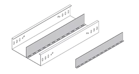
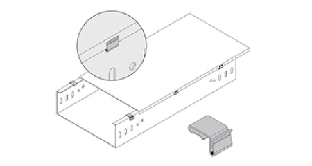
 Cable Ladder Cover Plate Fit, Joints and Service Access
Plan cover plates from measured rail seats, joint direction, clamp access and the route maintenance method. This page owns installation and retrofit fit.
READ MORE
-
Cable Ladder Cover Plates for Mechanical Protection and Dust Control
Specify a cable ladder cover by side-rail fit, panel edge, joint, clamp profile, material, finish and route conditions. The page separates dust and impact protection from any claim of a sealed enclosure.
READ MORE
-
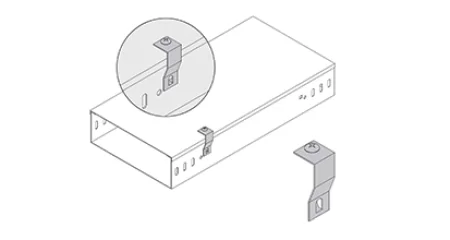
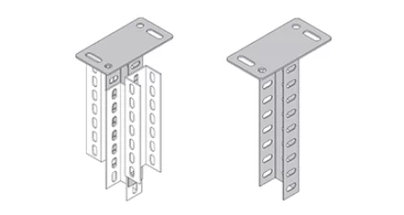
Cable Tray Support Systems: C-Channel Brackets, Hangers and Ceiling Supports
Select cable tray support systems by fixing surface, route geometry and load path, then coordinate bracket, channel, rod, fastener and finish before RFQ.
READ MORE
-
45 Degree Perforated Cable Tray Elbow for Gradual Horizontal Turns
A 45HE perforated tray elbow for shallow horizontal deviations, with catalogue A/B data, four material families, four finishes and drawing-based customisation.
READ MORE
-
ZAM Coated Perforated Cable Tray for Coastal and Marine Cable Routes
Zinc-aluminum-magnesium coated P1 perforated tray for coastal and marine routes, with ventilated support, compatible fittings, cut-edge inspection and project-specific load confirmation.
READ MORE
-
Aluminum Perforated Cable Tray for Lightweight Ventilated Routing
Aluminum perforated tray in 6061-T6 or 6063-T5, from 50 to 1200 mm wide, for lighter ventilated cable runs with catalog load data and matched fittings.
READ MORE
-
Stainless Steel Perforated Cable Tray (304/316) for Corrosive and Clean Environments
Choose 304 or 316 stainless perforated cable tray by exposure, then confirm the perforated section, support span, surface condition and complete stainless accessory package.
READ MORE
-
Pre-Galvanized Perforated Cable Tray Straight Sections for Control and Signal Cables
P1-01A pre-galvanized perforated cable tray straight sections support dry indoor control and signal routes, with EG coating classes, flexible dimensions, compatible accessories and documented quality checks.
READ MORE
-
Hot-Dip Galvanized Perforated Cable Tray Straight Sections for Outdoor Runs
Hot-dip galvanized perforated cable tray straight sections combine ventilated cable support, three HULK zinc options and catalog load data for exposed industrial routes.
READ MORE
-
Wire Mesh Cable Tray Y Junction for Angled Branch Routing
HULK Metal configures wire mesh cable tray Y junctions for angled branch routes, matched to tray width, side height, grid, wire, finish and support drawing.
READ MORE
-
Wire Mesh Cable Tray Straight Section
A 3000 mm HM-Q-W-01A welded-wire straight section for engineered cable routes, with standard widths to 600 mm, four materials and documented load and QC guidance.
READ MORE
-
WA-PB Wall Brackets with Upper Snap-Ons for Wire Mesh Cable Tray
A side-wall bracket for wire mesh cable tray, with an 84 mm plate, four arm lengths, two upper snap-ons and a CRP member, matched to 3.5-6 mm wire.
READ MORE
-
Wire Mesh Cable Tray V Connector for Raised-Floor Support
HULK Metal V Connector positions wire mesh cable tray under a raised floor, engages the pedestal support geometry and keeps the tray clear of removable floor panels.
READ MORE
-
Strengthening Bars for Wire Mesh Cable Tray Straight Joints
WA-STB joins two straight wire mesh tray sections with a 250 mm bar, three KK34-top clips, and matching M6 hardware for a longer clamp footprint.
READ MORE
-
HULK Metal Wire Mesh Cable Tray Standard Tee for Continuous Branch Routing
HULK Metal supplies wire mesh cable tray standard tees in mild steel, aluminium and stainless steel, with EG, HDG, ZAM or powder-coated finishes for project branch routes.
READ MORE
-
Wire Mesh Cable Tray Spider Bracket: Flat Fixing to Wall or Floor
WA-SB-9275 holds a wire mesh cable tray flat against a wall or floor. The formed plate hooks onto 3.5-6.0 mm tray wire and gives four 8.5 x 20.5 mm slots for the anchor bolts.
READ MORE
-
Side Bottom Buckle: The Fixing Point When No Bracket Fits
A hook-on plate for 4 mm wire mesh cable trays. It seats on the tray grid without bolts and gives equipment, boxes or a supplementary stay a Ø9 fixing point.
READ MORE
-
Radian Connector: The Curved Bar Behind a Wire Mesh Tray Bend
The radian connector is the curved bar kit that turns a wire mesh cable tray through a radius and closes T and cross junctions, sized to 50, 100 and 150 mm side heights.
READ MORE
-
M Shape Bars for Wire Mesh Cable Trays: Ceiling Suspension Sized by Tray Width
An M-section bar that hangs wire mesh cable tray from threaded rods, sized from 200 mm to 700 mm by tray width, with rods and nuts ordered as part of the same set.
READ MORE
-
L-Shaped Wall Brackets for Wire Mesh Cable Trays on Side Walls
One formed L bracket replaces a bracket-and-channel assembly on wall-hugging wire mesh runs. Four arm lengths cover trays from 100 mm to 300 mm wide on a shared 168 mm plate.
READ MORE
-
Hold Down Coupler for Wire Mesh Cable Tray: Wire-Matched Clamping for Risers and Supports
Hold down couplers clamp mesh tray runs at the wires themselves, keeping cables seated on vertical legs and fixing the tray to frames and stands. This page covers the interface, quantities and finishes.
READ MORE
-
Hanging Hook for Wire Mesh Cable Tray: Threaded Rod Suspension, Sized by Rod Diameter
A threaded hook is the rod-to-tray link in a suspended mesh tray run. This page covers rod sizing, the tray interface, anti-rotation locknuts, finishes and ordering checks.
READ MORE
-
Hanging Brackets for Wire Mesh Cable Trays: Ceiling Suspension Sized by Load Path
A hanging bracket joins a mesh tray to the ceiling structure, so it fits the tray wire and the rod above it. Load and spacing decide the part.
READ MORE
-
Fastlock Brackets That Lock Mesh Tray Onto C Channel Without Bolts
Fastlock seats a wire mesh tray on C-channel support framing without bolts at the tray, cutting installation time at the support position, with the channel profile confirmed before the order.
READ MORE
-
Push-In Splicers That Close Mesh Tray Joints Without Bolts
Screwless push-in splicers close straight wire mesh tray joints fast, listed as WA-DB-25025 for 3.5 to 6.0 mm wire, with bolted couplers where the run is wide or heavy.
READ MORE
-
Flush Drop In Anchors for Cable Tray Ceiling Fixing
Flush drop in anchors fix threaded rods and tray hangers into solid concrete ceilings, supplied in bolt-type sizes from D8 to D14 and internal threads from M6 to M12.
READ MORE
-
Cross Clips That Lock 90 Degree Wire Mesh Tray Crossings
Made cross clips fix the wire crossings a welded tray section cannot close, counted per junction and supplied in steel, 304 or 316 with four finish options.
READ MORE
-
One Clamp, Five Fittings: The KK34 Wire Mesh Coupler
Catalogue code WA-CKK34, 34 mm wide and 11 mm high, for wire mesh tray on 4.0 to 6.0 mm wire, and the top half that four bar-type connectors are built from.
READ MORE
-
KK28 Coupler: How Two Clamp Halves Join Wire Mesh Tray Sections
Catalogue code WA-CKK28, 28 mm wide and 11 mm high, for connecting straight wire mesh cable tray sections and making bends on trays from 3.5 to 5.0 mm wire.
READ MORE
-
Corner Strength Bars That Reinforce Wire Mesh Tray Tees and Crosses
Corner strength bars bolt across the cut corners of wire mesh cable tray bends, tees and crosses, adding a rigid steel member and four clips where the tray grid is opened.
READ MORE
-
Cable Guiders That Protect Wire Mesh Tray Drop-Out Points
HULK Metal cable guiders protect wire mesh tray entry and exit points with a formed curve, guarding cable jackets from cut wire ends and controlling the bend radius at every drop-out.
READ MORE
-
C Channel Brackets That Fix Wire Mesh Tray to Support Framing
HULK Metal C channel brackets connect wire mesh cable tray to support framing through a spring nut in the channel slot, with published series, lengths, thicknesses and load charts.
READ MORE
-
C Channel Support Framing for Wire Mesh Cable Tray Runs
HULK Metal C channel builds support frames for wire mesh cable tray in 41x41 and 83x41 profiles, with slotted faces, spring-nut fixing and support spacing taken from the tray load chart.
READ MORE
-
Two-Level Bridge Type Floor Stands for Wire Mesh Cable Tray
HULK Metal two-level bridge type floor stands carry a lower and an upper wire mesh cable tray run on one floor frame, with per-tier seats and drawing-confirmed tier spacing.
READ MORE
-
Bridge Type Floor Stands That Hold Mesh Tray Runs Above the Floor
HULK Metal bridge type floor stands support wire mesh cable tray on a two-post frame and cross beam, with a U-shaped seat, adjustable height and finish matched to the route.
READ MORE
-
Adjustable Connectors That Join Wire Mesh Cable Trays at Field-Measured Angles
HULK Metal adjustable connectors join wire mesh cable tray sections at site-measured angles with hinge, slotted halves and bolt locking, sized and finished to match the run.
READ MORE
-
Floor Stands Sized for 100 mm Wire Mesh Cable Tray
Factory-made 100 floor stands carry 100 mm wide wire mesh cable tray at floor and cabinet level with width-matched seats, hold-down options and batch QC records for bulk orders.
READ MORE
-
90 Degree Internal Riser Fittings for Wire Mesh Cable Tray Systems
Factory-made 90 degree internal riser fittings carry wire mesh cable tray through clean vertical level changes. Continuous welded grid, matched radius and drawing-based sizing protect cable bend limits in every batch.
READ MORE
-
Factory-Made 90 Degree Horizontal Bends for Wire Mesh Cable Tray
90 degree horizontal bends carry wire mesh cable tray through clean plan corners with matched radius and continuous welded grid. Volume supply with drawing-based sizing, matched finishes and batch QC records.
READ MORE
-
Floor Stands That Carry 50 mm Wire Mesh Cable Tray
A 50 mm floor stand raises wire mesh tray above floors and cabinet tops, keeps the run level, and pairs with hold-downs. Bulk supply with drawing-based sizing, finish options and batch QC records.
READ MORE
-
Factory-Made 45 Degree External Riser Fittings for Wire Mesh Cable Tray
45 degree external risers carry wire mesh cable tray through clean vertical level changes with pre-welded edges and protected cable radius. Bulk supply with batch QC records and drawing-based sizing.
READ MORE
-
Widening Connector Plates That Join Perforated Cable Trays at Different Heights
HULK Metal WCP connector plates join a perforated cable tray to a second run at a different height, with step sizes from WCP-50-50 to WCP-150-600 and four finish options.
READ MORE
-
Wall Brackets That Mount a Perforated Cable Tray to a Side Wall
HULK Metal WB wall brackets mount a perforated cable tray on a side wall, with arm lengths from WB-100 to WB-700, steel, aluminum and stainless options and EG, HDG, AZM or PC finishes.
READ MORE
-
Vertical Internal Bend Fittings for Perforated Cable Tray Level Changes
HULK Metal 02F vertical internal bends take perforated tray runs through level changes, in four angles, steel or stainless with EG, HDG and ZAM finishes.
READ MORE
-
Vertical External Bend Fittings for Perforated Cable Tray Level Changes
HULK Metal 02E vertical external bends take perforated tray runs through level changes, in four angles, steel or stainless with EG, HDG and ZAM finishes.
READ MORE
-
Under Floor Stand for Ground-Level Cable Tray Support
UFS-series under floor stands carry perforated cable tray bridges at ground level, with L sizes 100 to 500 mm, steel, aluminum and stainless options, four anti-corrosion finishes and a DIN EN IEC 61537 load basis.
READ MORE
-
Vertical Adjust Coupler for Cable Tray Level Changes
VAC-series vertical adjust couplers join perforated cable trays at level changes, sized by side height from 50 to 200 mm, in steel, aluminum and stainless with four finishes.
READ MORE
-
U Bracket Lifting Support Crossbar for Cable Tray
PA-series U brackets serve as lifting support crossbars for perforated cable trays, with L sizes 50 to 500 mm, steel, aluminum and stainless options, four anti-corrosion finishes and a DIN EN IEC 61537 load basis.
READ MORE
-
Tray Carrier for Perforated Cable Tray Joints
TC-series tray carriers join a perforated cable tray from both sides in 50 to 200 mm heights, in steel, aluminum or stainless steel with four anti-corrosion finishes.
READ MORE
-
Threaded Rod for Ceiling Cable Tray Suspension
HULK Metal supplies WA-LS and TR threaded rods for overhead cable tray runs, with catalogue lengths, hanger-pattern guidance and project-specific finish confirmation.
READ MORE
-
Cable Tray Right Reducer for Width Changes
RR-series right reducers step a perforated cable tray from a wide to a narrow width on the right side of the run, in steel, aluminum or stainless steel with four anti-corrosion finishes.
READ MORE
-
Cable Tray Raise Connection Piece for Height Transitions
RCP-series raise connection pieces carry a perforated cable tray from one side height to another at the end of a run, in steel, aluminum or stainless steel with four anti-corrosion finishes.
READ MORE
-
Outside Straight Coupler for Perforated Cable Tray
A join that keeps perforated cable tray runs level, continuous and rated for the same load as the tray, in OSC-50 to OSC-200 heights and four material and finish grades.
READ MORE
-
Middle Reducers That Narrow a Perforated Cable Tray Run Evenly
HULK Metal MR-series middle reducers step a perforated cable tray from a wider run to a narrower one with a centered taper on both sides, in standard and custom sizes with four finishes.
READ MORE
-
Left Reducers That Step Down Perforated Cable Tray Widths
HULK Metal LR-series left reducers step a perforated tray from a wider to a narrower run on one side, in standard and custom sizes with four finishes.
READ MORE
-
Inside Straight Coupler for Perforated Cable Tray
The HULK Metal inside straight coupler connects two perforated cable tray lengths in line, in ISC-50 to ISC-200 heights and the same grade and finish options as the tray.
READ MORE
-
Horizontal Cross Fittings for Perforated Cable Tray Systems
HULK Metal horizontal cross fittings join four perforated cable tray runs at one junction, in widths 50-1200 mm, in Q steel, aluminum or stainless with EG, HDG, AZM or PC finishes.
READ MORE
-
Horizontal Tee Fittings for Perforated Cable Tray Systems
HULK Metal horizontal tee fittings join a branch to a straight perforated cable tray run at one junction, in widths 50-1200 mm, in Q steel, aluminum or stainless with EG, HDG, AZM or PC finishes.
READ MORE
-
Hold Down Brackets That Lock Perforated Cable Trays to Their Supports
HULK Metal hold down brackets HDB-50 to HDB-200 fix perforated cable trays to C Channel 41x41 supports, with custom heights and finishes.
READ MORE
-
90° Horizontal Elbow for Perforated Cable Tray Systems
A 90° horizontal elbow turns a perforated cable tray run through a corner in the same plane while keeping the flange, the hole pattern and the load path continuous.
READ MORE
-
Perforated Cable Tray Dividers for Power, Control and Signal Separation
HULK Metal cable tray dividers separate power, control and signal cables inside perforated trays, in 3 m lengths and custom heights, with four finishes.
READ MORE
-
Cover Clamp 2 for Securing Cable Tray Covers
Cover Clamp 2 (CLP-CC2) secures cable tray cover panels in place, with custom heights and radii available, in the HULK Metal tray accessory range.
READ MORE
-
Cover Clamp 1 for Securing Cable Tray Covers
Cover Clamp 1 (CLP-CC1) secures cable tray cover panels in place, with custom heights and radii available, in the HULK Metal tray accessory range.
READ MORE
-
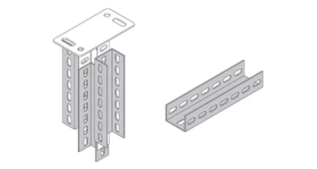
Ceiling Bracket-A with Vertical Posts for Cable Tray Support
Ceiling Bracket-A (CB A) suspends cable trays under ceilings with vertical posts and crossbar, heights 300-3000 mm, hot-dip galvanized, load tested to DIN EN IEC 61537.
READ MORE
-
Ceiling Bracket with Vertical Posts for Cable Tray Support
Ceiling brackets (CB and CB A) with vertical posts and crossbar suspend cable trays under ceilings, lengths 300-3000 mm, hot-dip galvanized, load tested to DIN EN IEC 61537.
READ MORE
-
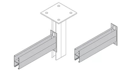
C Double Channel 83x41 Bracket for Heavy Cable Tray Support
Hot-dip galvanized C double channel brackets 83x41 (C83) with 14 mm holes, 200-1050 mm projections, for heavy cable tray and ladder support.
READ MORE
-
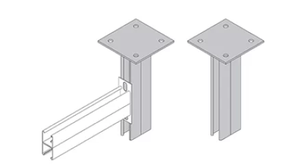
C Channel Hanging Support 83x41 for Heavy-Duty Cable Tray Suspension
Hot-dip galvanized C channel hanging supports 83x41 (CT83) with slotted surface, 14 mm holes, 500-2500 mm lengths, and safe working loads to 2.90 kN.
READ MORE
-
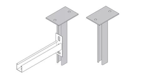
C Channel Hanging Support 41x41 for Cable Tray Suspension
Hot-dip galvanized C channel hanging supports 41x41 (CT41) with slotted surface, 14 mm holes, 250-2000 mm lengths, and safe working loads to 2.60 kN.
READ MORE
-
C Channel 41x41 Brackets That Carry Tray and Pipe Supports
HULK Metal C41 brackets for 41x41 C channel framing, in 100-900 mm lengths with HDG finish and published safe working loads.
READ MORE
-
C Channel 41x41 for Cable Tray Support Framing
HULK Metal C channel 41x41 framing for cable tray supports, in perforated and solid profiles with PG or HDG finish and spring nut fixing.
READ MORE
-
Cable Tray Bracket Frame for Ceiling Support
HULK Metal bracket frames lift perforated cable trays under ceilings. Five catalog codes cover 50 to 400 mm tray widths, with matched finishes for indoor and outdoor runs.
READ MORE
-
Cable Tray Bonding Jumper for Electrical Continuity
HULK Metal bonding jumper CL-BJ keeps perforated cable tray runs electrically continuous. Bridges coated joints and expansion gaps, with matched finishes for indoor and outdoor runs.
READ MORE
-
Cable Tray Bolt and Nut for Ceiling Suspension
HULK Metal bolt and nut sets suspend perforated cable trays under ceilings. Four catalog codes cover M6 to M12, with matched finishes for indoor and outdoor runs.
READ MORE
-
45 Degree Horizontal Bend for Wire Mesh Cable Tray
HULK Metal 45 degree horizontal bend is a factory-built wire mesh cable tray fitting matched to the straight section by width, height, and surface code for clean direction changes.
READ MORE
-
Straight Perforated Cable Trays Built for Ventilation and Load
HULK Metal straight perforated cable trays run 50-1200 mm wide with six folding edge types, four material codes, and four anti-corrosion finishes.
READ MORE
-
Perforated Cable Tray Blind Ends That Close Tray Runs Cleanly
HULK Metal BE-series blind ends close cable tray run ends in widths from 50 to 600 mm, with steel, aluminum, and stainless options and four anti-corrosion finishes.
READ MORE
-
Angle Bar Bracket for Cable Tray Support Systems
Angle bar bracket cable tray supports from HULK Metal carry trays as lifting crossbars in 50-500 mm lengths with custom finishes.
READ MORE
-
Vertical Tee Fitting-B Cable Trunking Fittings for Vertical Branches
Vertical tee fitting-B cable trunking fittings from HULK Metal add a vertical branch to a through run with custom sizes and finishes.
READ MORE
-
Vertical Tee Fitting-A Cable Trunking Fittings for Vertical Branches
Vertical tee fitting-A cable trunking fittings from HULK Metal add a vertical branch to a through run with published A and B dimensions.
READ MORE
-
Vertical Internal Bend Cable Trunking Fittings for Level Changes
Vertical internal bend cable trunking fittings from HULK Metal change run level in 30 to 90 degree steps with custom radius and finishes.
READ MORE
-
Vertical External Bend Cable Trunking Fittings for Level Changes
Vertical external bend cable trunking fittings from HULK Metal change run level in 30 to 90 degree steps with custom radius and finishes.
READ MORE
-
Vertical Cross Fitting-B Cable Trunking Fittings for Four-Way Junctions
Vertical cross fitting-B from HULK Metal joins four cable trunking directions at one junction, custom-built in EG, HDG, ZAM, or powder coating.
READ MORE
-
Vertical Cross Fitting-A Cable Trunking Fittings for Four-Way Junctions
Vertical cross cable trunking fittings from HULK Metal join four trunking directions at one junction, built to your width, height, thickness, and finish.
READ MORE
-
Upper Vertical Tee-B Cable Trunking Fittings for Rising Branches
Upper vertical tee-B fittings from HULK Metal carry a cable branch upward from a trunking run in Q steel, aluminum or stainless, with EG, HDG, ZAM and powder-coated finishes.
READ MORE
-
Upper Vertical Tee-A Cable Trunking Fittings for Rising Branches
Upper vertical tee-A fittings from HULK Metal carry a cable branch upward from a trunking run in Q steel, aluminum or stainless, with EG, HDG, ZAM and powder-coated finishes.
READ MORE
-
Upper Horizontal Cross-B Cable Trunking Fittings for Four-Way Junctions
Upper horizontal cross-B fittings from HULK Metal join four trunking runs at one intersection in Q steel, aluminum or stainless, with EG, HDG, ZAM and powder-coated finishes.
READ MORE
-
Upper Horizontal Cross Cable Trunking Fittings for Four-Way Junctions
Upper horizontal cross fittings from HULK Metal join four trunking runs at one intersection in Q steel, aluminum or stainless, with EG, HDG, ZAM and powder-coated finishes.
READ MORE
-
Slope Turn Cable Trunking Fittings for Inclined Routes
Slope turn fittings from HULK Metal change the gradient of a cable trunking run in Q steel, aluminum or stainless, with EG, HDG, ZAM and powder-coated finishes.
READ MORE
-
Left-Bottom Vertical Tee Fittings for Cable Trunking Drops
Left-bottom vertical tee fittings from HULK Metal turn a trunking run downward on the left side at a controlled 90 degrees, in Q steel, aluminum or stainless with EG, HDG, ZAM and powder-coated finishes.
READ MORE
-
Bell Mouth Fittings for Cable Trunking Entry Points
Bell mouth fittings from HULK Metal flare the end of a cable trunking run over a smooth radius, in Q steel, aluminum or stainless with EG, HDG, ZAM and powder-coated finishes.
READ MORE
-
Bottom Horizontal Cross-b Cable Trunking Fittings
The HULK Metal bottom horizontal cross joins two cable trunking runs at one junction, letting cables continue straight through or drop through the bottom outlet to machines, floor ducts, and panels below.
READ MORE
-
Cable Trunking Right Reducer
The HULK Metal right reducer connects cable trunking sections of different widths while keeping one side of the run flush.
READ MORE
-
Middle Reducer Cable Trunking Fittings
A middle reducer changes the width of a cable trunking run on one level, joining a wider section to a narrower one while keeping the route centered.
READ MORE
-
Left Reducer Cable Trunking Fittings
A left reducer changes the width of a cable trunking run while keeping one edge aligned, so cables stay supported where a wide trunking narrows toward outlets and panels.
READ MORE
-
Horizontal Tee Cable Trunking Fittings
A horizontal tee branches a cable trunking run into three directions on one level, feeding circuits to several destinations from a single line.
READ MORE
-
Horizontal Elbow Cable Trunking Fittings
A horizontal elbow changes the direction of a cable trunking run on one level, turning a route around corners and columns without changing its elevation.
READ MORE
-
Horizontal Cross Cable Trunking Fittings
A horizontal cross joins four cable trunking runs at a single intersection, turning one route into a four-way distribution point without changing elevation.
READ MORE
-
Cable Trunking Systems in HDG, EG, ZAM and PC Finishes
Cable trunking keeps cables enclosed, separated, and protected from dust, impact, and casual contact.
READ MORE
-
Left Reducer Cable Ladder Rack
A left reducer transitions the cable ladder width from a larger section to a smaller one, with the reduction occurring on the left side of the tray.
READ MORE
-
Horizontal Elbow Cable Ladder Rack Fittings
Horizontal elbows route cable ladders around obstacles while maintaining continuous support. HULK Metal offers full OEM services for elbows from 50 mm to 1200 mm widths, in any material and coating combination.
READ MORE
-
Horizontal Tee Cable Ladder Fittings
A horizontal tee isn’t a commodity—it’s a structural junction that reveals how well a manufacturer controls cutting, forming, welding, and coating.
READ MORE
-
Middle Reducer Cable Ladder Rack
A middle reducer connects two straight ladder sections of different widths, maintaining cable support continuity when the tray width must change due to varying cable counts or routing requirements.
READ MORE
-
Right Reducer Cable Ladder Rack
Right reducers appear simple, but poor fabrication leads to misalignment, cable stress, and costly delays. I’ll share factory-floor insights.
READ MORE
-
Vertical External Bend Cable Ladder Fittings
In cable ladder systems, the vertical external bend is one of the most geometrically demanding fittings. It changes direction upward and outward simultaneously.
READ MORE
-
Vertical Internal Bend Cable Ladder Fittings
A vertical internal bend handles the transition where cables must rise or fall within the same vertical plane while staying inside the ladder structure. It is not interchangeable with an external bend.
READ MORE
-
Horizontal Cross in Cable Ladder System
The horizontal cross is a crucial intersection in cable ladder networks, demanding precise geometry and robust construction. Our OEM service extends beyond simple branding: we tailor dimensions, surface finishes, and even rung spacing to your project specs.
READ MORE
-
Straight Cable Ladder Cable Ladder Rack
The straight cable ladder is not just a simple tray section. It's the primary load-bearing element that spans between supports. Its material, dimensions, and manufacturing quality directly determine whether cables are properly supported or whether the entire system sags, corrodes, or fails inspection.
READ MORE
-
Custom Network Server Tray
Discover the ultimate in custom network server tray design and manufacturing. At HULK Metal, we specialize in delivering bespoke solutions that meet every client's unique requirements with precision and reliability.
READ MORE
-
Laser Cutting Metal Parts Factory
We can develop a complete solution based on your server switch rack enclosure cabinets drawings, quantity, delivery time, transportation method and other requirements, allowing you to complete higher quality procurement tasks more easily.
READ MORE
-
Custom Metal Brackets Factory In China
We can select the appropriate process, make molds, and complete the production of metal brackets according to your drawings, materials, tolerances, quantities and other requirements.
READ MORE
-
Sheet Metal Spinning Parts Factory In China
HULK Metal is committed to providing high-quality sheet metal spinning parts OEM services to customers around the world. We have an ISO 9001 certified factory and integrated supply chain.
READ MORE
-
OEM Auto Metal Stamping Parts Factory
Our factory is certified by ISO 9001 and ISO 16949. Our experienced technical team can develop a more complete solution according to the drawings and requirements.
READ MORE
-
Stamped Steel Parts Factory
Stamped steel parts are made of carbon steel, alloy steel, and other plates into workpieces with specific shapes and functions using stamping processes such as blanking, bending, bulging, spinning, shrinking, flanging, etc.
READ MORE
-
Metal Stamping Parts Factory
HULK Metal is an ISO 9001 certified metal stamping factory that can provide you with high-quality OEM stamping services such as blanking, bending, drawing, forming, spinning, etc.
READ MORE




More Results
Process control from incoming metal to packing
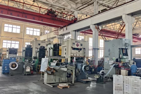
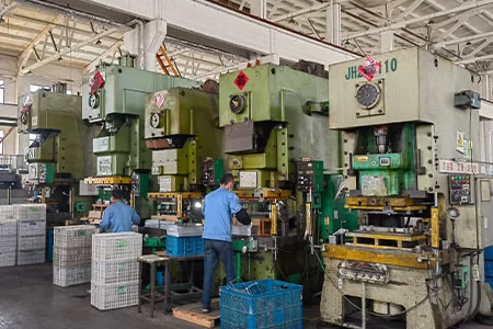
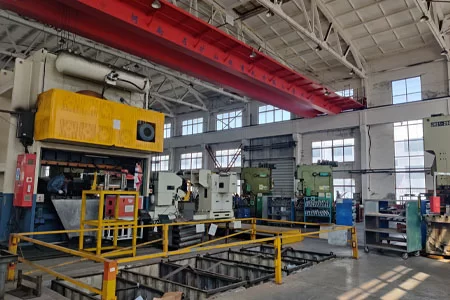
The ISO 9001 factory controls incoming material, cutting, punching, forming, welding, surface treatment, inspection and packing. Spectrometers, CMM, coating-thickness gauges and salt-spray chambers support material and finish checks; the purchase order still has to name which records and measurement points apply to the marine batch.


-
![Choose a Chinese OEM for Server Rack Trays]()
March 25, 2025
Choose a Chinese OEM for Server Rack Trays
READ MORE
-
![Metal Stamping OEM Factory in China]()
March 25, 2025
Metal Stamping OEM Factory in China
READ MORE
-
![HULK Metal Stamping Factory Show]()
November 21, 2024
HULK Metal Stamping Factory Show
READ MORE
-
![HULK Metal Fabrication]()
October 18, 2024
HULK Metal Fabrication
READ MORE
-
![Cable Tray Cost Drivers: Material, Coating and Quantity]()
November 14, 2026
Cable Tray Cost Drivers: Material, Coating and Quantity
READ MORE
-
![Waterproof Trunking: Where Sealed Cable Routes Actually Leak]()
November 09, 2026
Waterproof Trunking: Where Sealed Cable Routes Actually Leak
READ MORE
-
![Fabrication vs Machining vs Casting: A Metal Part Decision Guide]()
November 07, 2026
Fabrication vs Machining vs Casting: A Metal Part Decision Guide
READ MORE
-
![Automotive Sheet Metal Fabrication: Grades, Coatings and Tolerances]()
November 06, 2026
Automotive Sheet Metal Fabrication: Grades, Coatings and Tolerances
READ MORE
-
![Sheet Metal Ductwork Design: Sizing, Seams and Airflow]()
October 24, 2026
Sheet Metal Ductwork Design: Sizing, Seams and Airflow
READ MORE
-
![Powder Coating vs Plating for Sheet Metal Parts: Fit, Corrosion and Current Path]()
October 22, 2026
Powder Coating vs Plating for Sheet Metal Parts: Fit, Corrosion and Current Path
READ MORE
-
![Cable Tray Reducer Types: Concentric, Eccentric and Offset]()
October 21, 2026
Cable Tray Reducer Types: Concentric, Eccentric and Offset
READ MORE
-
![Cable Tray Load Tables: Read Span, Load and Deflection Before Approval]()
October 21, 2026
Cable Tray Load Tables: Read Span, Load and Deflection Before Approval
READ MORE
-
![Cable Tray Vertical Bend Guide: Metal Bending for Inside and Outside Risers]()
October 20, 2026
Cable Tray Vertical Bend Guide: Metal Bending for Inside and Outside Risers
READ MORE
-
![Tee vs Cross Fittings: When Cable Paths Branch]()
October 20, 2026
Tee vs Cross Fittings: When Cable Paths Branch
READ MORE
-
![Strut Channel Load Ratings: Match Profile, Axis and Fittings to the Support]()
October 19, 2026
Strut Channel Load Ratings: Match Profile, Axis and Fittings to the Support
READ MORE
-
![Fasteners vs Welding in Sheet Metal Assembly]()
October 19, 2026
Fasteners vs Welding in Sheet Metal Assembly
READ MORE
-
![Cable Tray Manufacturing: Six Control Points Between the Coil and the Container]()
October 16, 2026
Cable Tray Manufacturing: Six Control Points Between the Coil and the Container
READ MORE
-
![Metal Stamping Material Yield: Coil Width, Strip Layout and the Scrap You Pay For]()
October 16, 2026
Metal Stamping Material Yield: Coil Width, Strip Layout and the Scrap You Pay For
READ MORE
-
![How to Choose a Stamping Die: Matching the Tooling to Part Geometry and Volume]()
October 15, 2026
How to Choose a Stamping Die: Matching the Tooling to Part Geometry and Volume
READ MORE
-
![Cable Raceway vs Cable Tray: What US Buyers Mean and How to Specify]()
October 15, 2026
Cable Raceway vs Cable Tray: What US Buyers Mean and How to Specify
READ MORE
-
![Cable Tray Load Capacity: Working Out the Load Before You Choose the Span]()
October 13, 2026
Cable Tray Load Capacity: Working Out the Load Before You Choose the Span
READ MORE
-
![Metal Stamping Defects: From Symptom to Station to Fix]()
October 13, 2026
Metal Stamping Defects: From Symptom to Station to Fix
READ MORE
-
![Data Center Cable Tray Design - Segregation, Cooling and Access]()
October 12, 2026
Data Center Cable Tray Design - Segregation, Cooling and Access
READ MORE
-
![Powder Coating vs Galvanizing for Cable Trays: Where Each Finish Fails and How to Repair It]()
October 10, 2026
Powder Coating vs Galvanizing for Cable Trays: Where Each Finish Fails and How to Repair It
READ MORE
-
![OEM Sheet Metal Fabrication: From RFQ to Volume Production]()
October 10, 2026
OEM Sheet Metal Fabrication: From RFQ to Volume Production
READ MORE
-
![Fabrication QC Checklist: Dimensions, Weld and Finish]()
October 09, 2026
Fabrication QC Checklist: Dimensions, Weld and Finish
READ MORE
-
![Cable Ladder Incoming Inspection: The 7 Checks Buyers Keep Missing]()
October 08, 2026
Cable Ladder Incoming Inspection: The 7 Checks Buyers Keep Missing
READ MORE
-
![Sheet Metal Bending Defects: Causes, Fixes and the Pre-Shipment Checks]()
October 08, 2026
Sheet Metal Bending Defects: Causes, Fixes and the Pre-Shipment Checks
READ MORE
-
![Wire Mesh Cable Tray Installation - Cutting, Bending and Support On Site]()
October 08, 2026
Wire Mesh Cable Tray Installation - Cutting, Bending and Support On Site
READ MORE
-
![Cable Trunking Fittings: How a Run Turns, Branches and Steps Down]()
October 08, 2026
Cable Trunking Fittings: How a Run Turns, Branches and Steps Down
READ MORE
-
![MIG vs TIG vs Laser Welding for Sheet Metal]()
September 30, 2026
MIG vs TIG vs Laser Welding for Sheet Metal
READ MORE
-
![Tray, Conduit or Trunking: A Selection Guide]()
September 30, 2026
Tray, Conduit or Trunking: A Selection Guide
READ MORE
-
![Where Cables Enter and Leave a Cable Ladder System: Transitions, Bend Radius and Edge Protection]()
September 30, 2026
Where Cables Enter and Leave a Cable Ladder System: Transitions, Bend Radius and Edge Protection
READ MORE
-
![Bending Sheet Metal: Radii, Springback and Tooling]()
September 29, 2026
Bending Sheet Metal: Radii, Springback and Tooling
READ MORE
-
![Wire Mesh vs Solid Tray: Strength, Cost and Access]()
September 29, 2026
Wire Mesh vs Solid Tray: Strength, Cost and Access
READ MORE
-
![Cable Trunking vs Cable Tray: Protection and Access]()
September 28, 2026
Cable Trunking vs Cable Tray: Protection and Access
READ MORE
-
![Designing Sheet Metal Enclosures: Ventilation, Sealing and EMC]()
September 27, 2026
Designing Sheet Metal Enclosures: Ventilation, Sealing and EMC
READ MORE
-
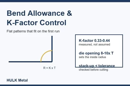
![How to Control Bend Allowance and K-Factor - A Shop-Floor Method for Sheet Metal Flat Patterns]()
September 27, 2026
How to Control Bend Allowance and K-Factor - A Shop-Floor Method for Sheet Metal Flat Patterns
READ MORE
-
![All 49 Cable Ladder Sizes, Their Published Load and Their Unit Weight]()
September 22, 2026
All 49 Cable Ladder Sizes, Their Published Load and Their Unit Weight
READ MORE
-
![Curved or Routine? Choosing the Right Cable Ladder Elbow for the Route]()
September 21, 2026
Curved or Routine? Choosing the Right Cable Ladder Elbow for the Route
READ MORE
-
![Cable Tray Fill Calculation: From a Cable Schedule to Width, Depth and Spare Capacity]()
September 14, 2026
Cable Tray Fill Calculation: From a Cable Schedule to Width, Depth and Spare Capacity
READ MORE
-
![Connecting New Tray to an Existing Run: Angles, Reducers and Tolerances]()
September 11, 2026
Connecting New Tray to an Existing Run: Angles, Reducers and Tolerances
READ MORE
-
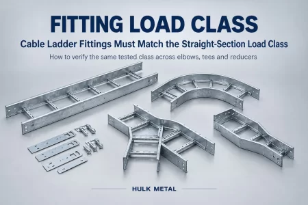
![Cable Ladder Fittings Must Match the Straight-Section Load Class]()
September 11, 2026
Cable Ladder Fittings Must Match the Straight-Section Load Class
READ MORE
-
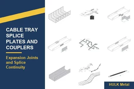
![Cable Tray Splice Plates, Couplers and Expansion Joints Explained]()
September 11, 2026
Cable Tray Splice Plates, Couplers and Expansion Joints Explained
READ MORE
-
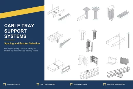
![Cable Tray Support Spacing and Bracket Selection: A Field Guide]()
September 11, 2026
Cable Tray Support Spacing and Bracket Selection: A Field Guide
READ MORE
-
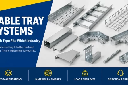
![Which Cable Tray Type Wins by Industry: A 2026 Selection Matrix for Data Halls, Solar Farms and Process Plants]()
September 10, 2026
Which Cable Tray Type Wins by Industry: A 2026 Selection Matrix for Data Halls, Solar Farms and Process Plants
READ MORE
-
![Comparing Cable Tray Quotes: The Five Data Points That Make Prices Comparable]()
September 07, 2026
Comparing Cable Tray Quotes: The Five Data Points That Make Prices Comparable
READ MORE
-
![Cable Ladder Systems for Heavy Industrial Runs: How to Spec Side Rails, Rungs and Load Ratings]()
September 05, 2026
Cable Ladder Systems for Heavy Industrial Runs: How to Spec Side Rails, Rungs and Load Ratings
READ MORE
-
![Pre-Galvanized, HDG, ZAM, Stainless or Aluminum: How to Buy Cable Tray Material That Matches the Site]()
September 05, 2026
Pre-Galvanized, HDG, ZAM, Stainless or Aluminum: How to Buy Cable Tray Material That Matches the Site
READ MORE
-
![Perforated vs Ladder vs Solid Cable Tray: When Each Fits Your Project]()
September 04, 2026
Perforated vs Ladder vs Solid Cable Tray: When Each Fits Your Project
READ MORE
-
![Cable Tray Installation: A Field Guide to Supports, Spacing and Bonding]()
August 19, 2026
Cable Tray Installation: A Field Guide to Supports, Spacing and Bonding
READ MORE
-
![2026 Cable Tray Trends: Renewables and Data Halls Reshape the Specification]()
August 18, 2026
2026 Cable Tray Trends: Renewables and Data Halls Reshape the Specification
READ MORE
-
![Metal Deep Drawing: A Comprehensive Guide]()
March 24, 2025
Metal Deep Drawing: A Comprehensive Guide
READ MORE
-
![Comprehensive Guide to Sheet Metal Bending]()
March 21, 2025
Comprehensive Guide to Sheet Metal Bending
READ MORE
-
![Sheet Metal Spinning]()
March 21, 2025
Sheet Metal Spinning
READ MORE
-
![A Suitable OEM Factory for Your Network Server Blank Panels]()
February 28, 2025
A Suitable OEM Factory for Your Network Server Blank Panels
READ MORE
-
![Common Network Server Accessories: A Complete Guide]()
February 28, 2025
Common Network Server Accessories: A Complete Guide
READ MORE
-
![A Comprehensive Guide to Network Server Racks]()
February 26, 2025
A Comprehensive Guide to Network Server Racks
READ MORE
-
![Superior Network Server Cable Management Solutions by HULK Metal]()
February 24, 2025
Superior Network Server Cable Management Solutions by HULK Metal
READ MORE
-
![Choose a Suitable OEM Factory to Produce Your Network Server Racks]()
February 21, 2025
Choose a Suitable OEM Factory to Produce Your Network Server Racks
READ MORE
-
![Comprehensive Guide to Sheet Metal Spinning]()
December 04, 2024
Comprehensive Guide to Sheet Metal Spinning
READ MORE
-
![Introduction to Sheet Metal Forming: Processes, Materials, and Choosing the Right Partner]()
October 29, 2024
Introduction to Sheet Metal Forming: Processes, Materials, and Choosing the Right Partner
READ MORE
-
![Comprehensive Guide to Sheet Metal Cutting: Methods, Materials, and Choosing the Right Partner]()
October 25, 2024
Comprehensive Guide to Sheet Metal Cutting: Methods, Materials, and Choosing the Right Partner
READ MORE
-
![Comprehensive Guide to Sheet Metal Blanking]()
October 24, 2024
Comprehensive Guide to Sheet Metal Blanking
READ MORE
-
![Comprehensive Understanding of Sheet Metal Welding]()
September 30, 2024
Comprehensive Understanding of Sheet Metal Welding
READ MORE
-
![The Most Comprehensive Introduction To Metal Stamping Dies]()
September 24, 2024
The Most Comprehensive Introduction To Metal Stamping Dies
READ MORE
-
![Introduction to Metal Stamping Processes]()
September 19, 2024
Introduction to Metal Stamping Processes
READ MORE







Previous article: None
Next article: Cable Tray Cost Drivers: Material, Coating and Quantity
More cable tray engineering and sourcing guides
leave a message