

MIG, TIG and laser welding put very different amounts of heat into the same sheet metal part, and heat input is what decides whether it stays flat, how much grinding follows, and what the joint costs per piece.

Heat input and volume decide which welding process a sheet metal part can tolerate.
MIG vs TIG vs Laser Welding for Sheet Metal
-
Home>
-
Blog>
-
Technology>
MIG vs TIG vs Laser Welding for Sheet Metal
30
2026.09
Sheet metal welding is a process-selection problem before it is a skill problem. The same 2 mm bracket can be welded three ways and pass inspection every time, with very different consequences for flatness, grinding hours and cost per piece. This guide works from the one figure that predicts all three: heat input per millimetre of weld.
Why the Same Sheet Metal Part Gets Three Different Welding Processes
Send one welded bracket to three fabricators and you can get three answers back: MIG, TIG, or laser. None of them is wrong. Sheet metal welding is a process-selection problem before it is a skills problem, and the four numbers that drive the selection are usually missing from the drawing.
A 1.5 mm cold-rolled cover and a 6 mm mounting plate are both "sheet metal" inside a purchasing system. To the welder they sit at opposite ends of one decision. Thin sheet loses flatness the moment heat goes in. Thick sheet accepts heat comfortably but takes longer to fill and often needs joint preparation before the first arc.
Process choice then moves with volume: a prototype can afford a slow, controlled bead, a 5,000-piece run cannot. When a quotation names a process, it is naming the answer to that whole set of constraints.
✓ Material thickness, and whether the part is still flat after cooling
✓ Heat input per millimetre of weld, not the number printed on the machine dial
◦ Annual volume, part size, and how much handling the joint allows
◦ Whether the seam must be watertight, painted over, or left bare
The four pull against each other. Laser wins the flatness argument on thin stainless and loses it on a structural fillet that has to carry load. MIG wins on deposition rate and loses on a 0.9 mm panel that discolours around the bead. TIG threads between them and charges for the time it spends there.
The useful question is not which process is better, but which the part can tolerate given its thickness, its quantity and what happens to it afterwards: first the physics that limits every process, then the practical window for each one, then a decision matrix you can read off a drawing.
Any figure here describes how a process behaves on steel sheet in general, not the settings a shop will run on your job. Where a detail is drawing-specific, the honest answer stays Contact us for details.
Heat Input Is the Number That Decides Everything Downstream
Heat input per unit length predicts how much a welded sheet metal part will move. It is written in joules per millimetre, and two processes running at a similar-looking bead size can differ by half again in what they put into the panel.
Industry measurements put typical MIG welding at 200 A near 1.2 kJ/mm, while TIG at 150 A runs around 0.8 kJ/mm. Those are process-level figures rather than machine specifications, and they explain the trade every fabricator makes: MIG deposits faster and heats harder, TIG deposits slowly and heats less.
Table 1. Operating envelope, published heat input, and the distortion each process leaves on steel sheet.
| Process | Typical envelope on sheet | Published heat input | How the panel reacts |
|---|---|---|---|
| MIG / MAG | 200 A class on structural thickness | ≈ 1.2 kJ/mm at 200 A | Angular pull; burn-through below roughly 1 mm |
| TIG | 150 A class, thin sheet, hand control | ≈ 0.8 kJ/mm at 150 A | Narrow heat band; slow travel soaks the strip |
| Fibre laser | 400–1000 W class for sheet metal | Narrow, deep pool instead of a wide arc | Least long-range bow; unforgiving on fit-up gaps |
| Resistance spot | 4–8 kA through lapped sheets | No travelling arc at all | Local electrode mark; nugget diameter ≈ 5√t |
The distortion response is not linear in heat, and not linear in thickness either. Angular distortion scales roughly with heat input divided by thickness squared, which is the most useful relationship in this subject. Double the thickness and angular distortion falls to about a quarter at the same heat input; halve the travel speed and it roughly doubles.
→ Thin sections under about 3 mm show up as angular distortion: the flange rotates around the weld
→ Sections over about 10 mm show up mainly as longitudinal shrinkage along the joint
→ A 12 mm butt weld with a 40 mm² deposit and a 3 mm gap contracts roughly 0.82 mm across the joint
Those figures land in the tolerance stack. Coatings applied afterwards add their own thickness on top, so a welded, powder-coated assembly is not a flat blank plus paint: a 60–120 µm layer will not close a 2 mm hole, but it will change whether a fastener still drops in.
This is where a shop chooses between fighting distortion and avoiding it. Avoiding it means a lower-heat process or a different joint. Fighting it means sequence planning, fixturing and straightening hours, all of which appear on the quotation.
MIG Welding Sheet Metal: Deposition Rate and the Thickness Window
MIG welding sheet metal earns its place through deposition: wire feeds continuously, so the operator fills a joint in one pass where TIG would need several. That same continuous feed is why MIG stops being the right answer as the sheet gets thinner.
The process is normally described as the choice for larger parts made from thicker material, including structural steel. On sheet it behaves best in a middle band where the panel can absorb the arc without losing its shape. Below that band, the wire feed that makes MIG productive is the reason the part burns through before the operator can react.
Table 2. Where MIG works on sheet, and what goes wrong outside that band.
| Thickness band | What MIG needs to behave | What happens if it is ignored |
|---|---|---|
| Finer than 22 gauge (≈ 0.76 mm) | Most shops move to spot welding, TIG, or mechanical fastening | Burn-through becomes the normal outcome, not the exception |
| 0.8 – 1.5 mm | Short passes, tight fit-up, a chill bar where the seam is long | Edge burn-back and visible angular pull along the seam |
| 1.5 – 3.0 mm | The comfortable band for covers, frames, brackets and bases | Little trouble unless a full continuous seam is run without a break |
| 3.0 – 6.0 mm | Single-pass fillets; deposition rate is the reason to be here | Heat accumulates where thick sections meet thin ones |
| Over 6 mm | Bevels, several passes, attention to interpass temperature | Longitudinal shrinkage along the joint rather than local bowing |
Deposition and heat input travel together on MIG, and that is the honest trade. At 200 A the process puts roughly 1.2 kJ/mm into the part, about half again the heat of a 150 A TIG bead. The extra heat buys speed on a bracket and costs flatness on a panel.
✓ Choose MIG when the joint must be filled quickly and the surrounding metal can take the heat
◦ Choose something else when the sheet is thinner than 22 gauge or the panel must stay cosmetic
● Expect grinding time on any MIG seam that will be seen or painted
Grinding is the cost that surprises buyers. A MIG bead leaves spatter and a crown that has to come down before coating, and a painted enclosure shows every wave that was not flattened first. Whether that matters is a drawing question: a bracket inside a machine can look like anything, a front panel cannot.
TIG Welding Thin Sheet Metal: Where Distortion Sets the Limit
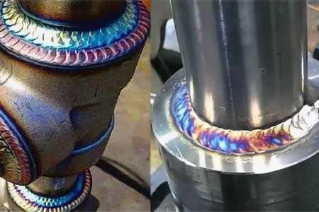
TIG welding thin sheet metal is the process fabricators reach for when the panel has to stay flat and the seam has to look untouched. It puts roughly 0.8 kJ/mm into the part at 150 A, less than a MIG bead at 200 A, and it lets the operator steer the pool instead of aiming a wire feed at it.
The price is time. Because travel speed is low, the same joules stay in the part longer, so heat spreads along a narrow strip beside the weld. On a 1 mm stainless cover that strip is exactly where the bow appears, which is why TIG control is mostly a series of decisions taken before the arc starts.
-
Step 1 — Fix the fit-up before the arc
Tack so the gap stays consistent along the joint; TIG has little tolerance for a gap that opens and closes. Uneven tacks introduce their own stress before the seam is run.
-
Step 2 — Weld in segments, not in one run
Industry skip patterns typically use 50–75 mm weld segments separated by 25–50 mm gaps, with the skipped sections closed afterwards in reverse order.
-
Step 3 — Let the part cool between segments
Interpass temperature keeps a multi-run seam from behaving like one continuous heat soak. On thin sheet the pause is often longer than the weld.
-
Step 4 — Check flatness while the part is still clamped
Measuring after the fixture is released is measuring too late. A bowed cover caught before release can still be brought back with counter-heat or a controlled clamp load.
✓ Aluminium 5052-H32 usually wants an inside bend radius of 1–1.5 times thickness, and 6061-T6 wants more
◦ Stainless needs the heat moved through quickly; holding it in the chromium-carbide range causes sensitisation
◦ Galvanised sheet should have the zinc ground back from the weld zone before the arc starts
That stainless constraint cuts against the usual advice. Slowing down is the standard way to control distortion, but on stainless the slow route holds the material in the range where chromium carbides precipitate at the grain boundaries. The fix is not to weld slower; it is to design the joint so less weld is needed.
TIG also opens a design decision that saves more than weld time: a formed corner needs no filler, no grinding and no finishing, so forming instead of welding removes an operation from the route. Where a drawing arrives with a 1 mm cosmetic seam and a flatness callout, the appearance requirement and the quantity set the segment length.
Laser Welding Sheet Metal: When a Grind-Free Seam Pays for Itself
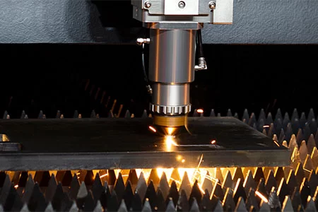
Laser welding sheet metal uses a focused beam, typically a 400–1000 W fibre source for sheet work, to create a narrow, deep pool instead of a wide arc. The pool is small; that is the whole point. Less surrounding metal gets hot, so the panel keeps the shape it had before welding.
The consequences arrive in a predictable order: the seam usually needs no filler and produces almost no spatter, so the grinding step after a MIG bead can disappear from the route; and flatness that a MIG or TIG seam would pull out of a thin cover survives instead. Both are finishing savings rather than welding savings, which is why they are easy to miss when comparing process costs.
Thin stainless and cold-rolled covers where the flatness callout is tighter than the process can distort. This is the strongest case, because a narrow keyhole pool puts very little heat into the panel either side of the joint.
Seams that will be seen. A laser bead is narrow and clean enough that the cosmetic step before coating is often a wipe rather than a grind.
Variable gaps. A laser will not bridge a gap that opens and closes along a seam the way a MIG bead will, so fit-up becomes a hard requirement rather than good practice.
One-offs and short runs, where fixture time and programming sit on the front of the job with no volume to spread them across.
The route shortens: weld, then straight to surface treatment. On coated parts that matters twice over, because a flatter panel needs less filler work under a 60–120 µm powder layer.
Inspection changes too. A narrow, consistent bead is easier to judge visually, but it leaves less material to absorb an error, so first-article checks carry more weight than they do on a heavy MIG seam.
Table 3. What laser welding buys on sheet, and the limits that come with it.
| What it buys | Why that follows from the process | Limit to plan around |
|---|---|---|
| Flatness on thin sheet | Narrow, deep pool; small heat-affected zone | Distortion is reduced, not eliminated; fixtures still matter |
| Less finishing | Minimal spatter, no filler wire, tight bead profile | A visible undercut cannot be hidden with a grinder |
| Speed on repeat work | Travel speed held by machine motion rather than by hand | Programming and fixture cost lands on the first part |
| Access to tight geometry | The beam reaches joints a torch cannot approach | Joint must be designed for the beam, not for a torch |
The cost comparison is not machine rate against machine rate. It is the whole route: laser, clean, coat, against MIG, grind, straighten, clean, coat. On a painted enclosure with a flatness callout the second route carries hours that never appear in a per-metre welding rate.
Spot, Stitch and Plug Welding: Buying Speed Back with Less Heat
Three joining methods sit between a full seam and a mechanical fastener, and all three exist for the same reason: a continuous bead puts more heat into the part than the part needs. Choosing where to stop welding is often the cheapest distortion control available.
Resistance spot welding passes a high current, typically 4–8 kA for sheet, through two copper electrodes clamping lapped sheets. There is no travelling arc, so the heat is confined to the nugget under the electrode. Nugget diameter follows a simple shop rule, roughly five times the square root of sheet thickness: two 1 mm sheets give a nugget near 5 mm.
✓ Spot welding suits lapped joints on 0.8–2.0 mm sheet where speed matters more than appearance
✓ Stitch welding leaves gaps by design and cuts cumulative heat input by 50–70% against a full seam
● Plug welding fills a hole or slot to join overlapping parts and concentrates heat in one spot
» Below 22 gauge, most shops leave fusion welding altogether for spot, TIG or mechanical fastening
Stitch welding is the one buyers most often overlook. Replacing a 500 mm continuous fillet with a pattern such as 20 mm of weld followed by a 30 mm gap removes most of the heat while keeping far more than enough strength for an enclosure frame. The seam is not watertight, which is the trade: if the part has to keep liquid or dust out, stitch welding is the wrong answer regardless of how much it saves.
Watch the plug weld. Filling a hole concentrates heat in one place, needs the most cleaning of any of these methods, and is not watertight. On thin sheet it is the joint most likely to leave a visible pull.
The relative cost ranking is stable across shops: stitch welding is cheaper than welding a full seam, full-seam fillet welding creates a strong watertight joint but needs the most cleanup, and plug welding sits in the middle on cost while sitting last on reliability for cosmetic parts. What moves the ranking is the inspection requirement, because a stitch weld cannot pass a leak test no matter how well it is executed.
There is also a design route that removes welding entirely rather than reducing it. Tabs and slots can locate parts without a weld, self-clinching fasteners can replace tapped holes, and hems can give a safe edge without manual deburring.
The Decision Matrix: Thickness × Annual Volume Picks the Process
Two inputs settle most process arguments before anyone reaches for a torch: how thick the sheet is, and how many parts a year are needed. The matrix below maps those two against the six joining methods already covered.
Read it as a starting position rather than a verdict. Each cell names the process that usually wins at that combination, and the five notes underneath explain the reasoning by thickness band, because thickness is the input that constrains the process hardest.
Table 4. Sheet thickness against annual volume. Select a cell to see the recommended process.
| Sheet thickness | 1–25 / year | 26–250 / year | 251–2,000 / year | 2,000+ / year |
|---|---|---|---|---|
| Finer than 22 ga (≈ 0.76 mm) | TIG | TIG | Laser | Spot / laser |
| 0.8–1.5 mm | TIG | TIG or laser | Laser | Laser |
| 1.5–3.0 mm | TIG or MIG | MIG | Laser or MIG | MIG + fixture |
| 3.0–6.0 mm | MIG | MIG | MIG + stitch | MIG + stitch |
| Over 6.0 mm | MIG, multi-pass | MIG, multi-pass | MIG, multi-pass | MIG, multi-pass |
Recommended process: select a cell above Cells are a starting position, not a quotation.
→ Finer than 22 gauge: the sheet cannot absorb a travelling arc, so the process has to stop moving or stop being an arc
→ 0.8–1.5 mm: heat input decides, and volume decides whether hand control is affordable
→ 1.5–3.0 mm: the widest band, where the finish callout usually breaks the tie
→ 3.0–6.0 mm: deposition wins, and stitch patterns are how you keep the heat down anyway
→ Over 6.0 mm: pass count and welding sequence carry the job, not the process name
Two other inputs can override a cell. A watertight requirement rules out anything stitched or spotted. A flatness callout tighter than the thickness can hold rules out full-seam MIG on thin sheet no matter how the volume reads. Both of those live on the drawing, which is why a matrix can shorten a discussion but cannot replace the drawing.
If two cells could describe your part, that doubt is worth resolving before tooling is cut: send the thickness range, quantity, and finish callouts.
Fit-Up and Joint Design Rules That Narrow the Choice
Most welding problems on sheet metal parts are designed in before the first arc. The rules below change which process is even possible, so they belong on the drawing review.
The first is flange length. Air bending needs enough material to sit in the die, and the figure that governs it is the die opening rather than a fixed multiple of thickness: roughly 0.7 times V. A shorter flange will not form cleanly, and a formed-then-welded corner loses the alignment the weld depends on.
Table 5. Design rules that constrain welding, with the figure behind each one.
| Rule | Working figure | Effect on the weld |
|---|---|---|
| Minimum flange for air bending | ≈ 0.7 × die opening (V) | Short flanges do not form square, so the joint gap varies |
| Hole edge to bend tangent | ≥ 2 × material thickness | Closer than that, the hole deforms and the joint will not pull up |
| Any feature to a bend line | ≥ 2 × material thickness | Distortion near the bend means rework before welding starts |
| Bend angle tolerance | ± 1° is common industry practice | Stacked bends decide whether the joint closes without force |
| Hole tolerance before welding | Laser-cut ± 0.005–0.010 in; punched ± 0.010–0.015 in | Sets the fit-up a laser or TIG joint needs to work at all |
| Tolerance after welding | Assemblies commonly held to ± 0.030 in | A tighter drawing needs fixturing, not a better welder |
The second half of the problem is the joint type, because each one presents the heat differently to the same thickness of material.
Butt joints put the whole heat input straight through the plate thickness. They suit laser and TIG on thin sheet, need a consistent gap, and shrink along the joint line, which is why a long butt seam pulls a panel end to end rather than locally.
Lap joints are the natural home of resistance spot welding, since the electrodes only need access to two flat faces. They tolerate a variable edge position far better than a butt joint, which is why spot welding survives on parts where laser would demand perfect fit-up.
Fillet and T joints concentrate heat at the root of one side, so the flange rotates. Balanced fillets on both sides are the standard countermeasure: net angular distortion typically falls to roughly ten to twenty percent of the single-sided value.
Corner joints on a folded box are where forming should be considered before welding. A formed corner carries no filler, no grinding and no finishing, and it removes a distortion source rather than controlling it.
Fix the gap, not the arc. A joint whose gap opens and closes along its length will be welded twice: once badly, once after the fit-up is corrected.
Taken together, these rules usually remove half the matrix on their own. A part with a 6 mm mounting flange and a 1 mm cosmetic cover is two welding jobs on one drawing.
Distortion Control on the Floor: Sequence, Pre-Set and Restraint
Distortion is not random. It is the predictable result of restrained thermal expansion followed by contraction, which means it can be planned for rather than chased afterwards. The five steps below are the order in which a welded sheet metal assembly is usually kept square.
Why clamping alone does not fix it
A common assumption on the shop floor is that a heavy clamp will hold a part flat. It will not. Restraint changes how much of the contraction turns into plastic strain, but the strain is still there; when the clamps come off, the stored stress comes out as movement.
1
Plan the sequence before the fixture is built
Decide the order of every weld on the assembly. Sequence is the most overlooked control, and it costs nothing but planning time.
2
Tack symmetrically, then check the gap
Tacks hold alignment, but unevenly spaced tacks introduce their own local stress. Space them so the joint pulls up evenly.
3
Break long seams into segments
Skip patterns commonly run 50–75 mm of weld followed by 25–50 mm of gap, with the gaps closed in reverse order. Back-stepping does the same job by welding against the direction of travel.
4
Set the joint against the expected pull
If a fillet weld on one side of a T joint typically pulls the plate three degrees, the plate is set three degrees the other way, and the finished part lands flat.
5
Measure before releasing the clamps
Flatness and hole position are worth checking while the assembly is still restrained. Once it is free, the options are heat straightening or scrap.
● Balanced welds on both sides of a T joint bring net angular distortion down to roughly 10–20% of the single-sided figure
● Stitching a 500 mm fillet to a 20 mm / 30 mm pattern cuts cumulative heat input by 50–70%
✓ Interpass temperature matters most on multi-run seams: letting the part cool between runs is a control, not a delay
On our own floor the sequence plan is written onto the job before the fixture is set, because once a welder is working to a rhythm the cheapest moment to change the order has passed. Where a flatness callout is tighter than the assembly tolerance we would normally hold after welding, the fixture has to be designed for it, and that surfaces at drawing review rather than at the bench.
The economics are simple: every hour spent straightening a part is an hour the upstream plan should have removed, and an hour a competitor quoting the same part may not have counted at all.
Welding Coated, Stainless and Aluminium Sheet
Material decides which process is available before thickness gets a vote. Galvanised sheet, austenitic stainless and the 6000-series aluminium alloys each remove options from the matrix, and each does it for a different reason.
Start with galvanised, because it is the most common surprise. The problem for welding is the coating rather than the steel. Zinc vaporises well below the melting point of steel, so it boils out of the pool and gets trapped as the weld solidifies, producing porosity and a rough bead. Where the coating is thick it also throws up the white plume that gives galvanised welding its reputation.
Table 6. Coating and alloy effects that change the welding plan.
| Material / coating | What changes | What it costs if ignored |
|---|---|---|
| Hot-dip galvanised sheet (A653, 0.5–2.0 mils) | Zinc ground back from the weld zone before the arc | Porosity in the bead and fume above exposure limits |
| Hot-dip structural galvanising (A123, 3.0–5.0 mils) | Thicker coating means more fume and more cleanup | Weld quality drops and the extraction load rises |
| Electrogalvanised and galvanneal (0.1–1.5 mils) | Lighter coating, so less fume at the same current | Still enough zinc to cause porosity if not removed |
| Powder-coated blanks (60–120 µm) | Coating cannot survive the weld; weld first, coat after | Burned coating and a repair that shows through the finish |
| Aluminium 5052-H32 | Bend radius around 1–1.5 times thickness keeps the corner intact | Cracking at the formed corner before welding begins |
| Aluminium 6061-T6 | Crack-sensitive; needs generous radii and a matched filler | Hot cracking in service, not at inspection |
| Austenitic stainless | Move heat through quickly; avoid a long dwell in the sensitising range | Sensitised grain boundaries and reduced corrosion resistance |
The extraction numbers are legal limits rather than preferences. Zinc oxide fume carries an OSHA permissible exposure limit of 5 mg/m³ as an eight-hour average, an ACGIH threshold limit of 2 mg/m³, and a short-term limit of 10 mg/m³ over fifteen minutes. Measurements taken in a welder's breathing zone without ventilation have come back between 10 and 50 mg/m³. The particles are 0.01–0.1 µm, below the size range an N95 filter is rated for.
Grinding is the control. Removing the zinc from the weld zone eliminates both the fume hazard and the porosity problem in one step. Technique changes reduce weld defects; they do not reduce exposure.
✓ Design for the coating rather than around it: weld first, then galvanise or coat, where the route allows
» Match the filler to the base alloy on aluminium; a mismatched filler is a service-life problem
◦ Specify a low-carbon stainless grade where a lot of welding lands on one assembly
One consequence for buyers: the same drawing in galvanised sheet and in cold-rolled sheet is not the same job.
Weld Inspection and Acceptance for Sheet Metal Parts
Sheet metal weld inspection starts by naming the discontinuities that actually occur on thin-gauge work, then matching a detection method to each one. Most of what goes wrong on a 2 mm seam is visible, and most of what is not visible is a distortion problem rather than a weld problem.
The acceptance framework most sheet steel work falls under is AWS D1.3/D1.3M, the sheet steel welding code, in its 2025 edition. It covers welder qualification, prequalified paths for common joints, joint preparation and fit-up guidance, and acceptance criteria for discontinuities. On structural members the equivalent document is AWS D1.1.
Table 7. Discontinuities on welded sheet metal, their origin, and how each is caught.
| Discontinuity | Where it comes from | How it is found |
|---|---|---|
| Porosity | Zinc, oil or oxide boiled into the pool | Visual on the surface; ultrasonic for buried pores |
| Undercut | Too much current, or travel too fast at an edge | Visual and dimensional check against the drawing |
| Burn-through | Arc on sheet finer than the process tolerates | Visual; usually caught at the bench |
| Cold lap / lack of fusion | Fit-up gap or travel speed mismatch | Visual for surface lap; ultrasonic or penetrant for the rest |
| Cracking | Crack-sensitive alloys, restraint, or wrong filler | Penetrant for surface-breaking cracks; ultrasonic through section |
| Distortion | Heat input against thickness, and weld sequence | Dimensional check of flatness and hole position |
| Spatter and surface finish | Process choice, shielding, and cleaning before coating | Visual; matters most before a cosmetic finish |
Where the weld carries load, inspection moves past the surface. Penetrant testing finds surface-breaking defects on thin plate and on non-ferrous material with no special equipment, which is why it is the usual second step after a visual pass. Ultrasonic testing goes after buried defects, and destructive tests stay on samples rather than finished parts.
The first and most economical pass. On sheet metal it covers porosity at the surface, undercut, burn-through, spatter and obvious lack of fusion, and it is where distortion is noticed because the inspector has the part in hand.
A dye penetrant is drawn into open defects and revealed by a developer. It finds surface-breaking cracks and laps on thin plate and on aluminium or copper alloys, and it cannot find anything buried. That limitation is also its advantage: it reports what is open to the surface, where most service cracks start.
Ultrasonic testing looks through the section for internal defects, and phased-array versions image the weld more precisely than a single probe. It needs a trained operator and a written procedure.
Tensile, impact, bend and hardness tests break the sample. That makes them unsuitable for finished parts and very suitable for process qualification: they are how a shop proves a welding procedure produces the properties the drawing assumes.
Tolerance budget on a welded, laser-cut part
Read that chart as a budget rather than a score. The hole is cut before anything is welded, so the cut tolerance is one line in the stack; the welded assembly is held looser because the heat has already been through it. A drawing calling for ± 0.005 in across a welded joint is asking for a machining operation after welding.
Inspection scope belongs in the purchase order: a visual check on every part, a penetrant check on a sample, and a dimensional report on the first article are three levels of assurance at three prices.
What Actually Drives Cost per Welded Part
Welding time is rarely the largest line in a welded sheet metal quotation. The drivers that move the price most are the ones wrapped around the weld: preparation, grinding, straightening, inspection and the finish that has to survive all of them.
Start with labour, because it multiplies everything else. General fabrication shops typically bill in the range of 90 to 200 US dollars per hour, with tight-tolerance or multi-axis work priced at the top of that band. A process that adds twenty minutes of grinding per part therefore adds cost at the same hourly rate as the welding itself.
Preparation and fit-up
Cutting accuracy, deburring and jig time all sit before the arc. Accurate flat blanks reduce gap fill and distortion during weld-up, so money spent on the blank is often money saved at the bench.
Grinding and finishing
Deburring, welding, drilling, grinding and polishing are commonly quoted together at roughly 0.20 to 2.00 dollars per part depending on how visible the result has to be.
Distortion and rework
Straightening is unplanned labour. Secondary operations such as welding and finishing can conceal a 30 to 50 percent impact on true lead time, which is why a quote that lists them separately is easier to compare.
Inspection
A visual pass costs almost nothing per part; a dimensional first-article report and penetrant sampling cost real hours. Tighter tolerances pull more inspection and a higher scrap rate behind them.
Part complexity then decides how much of each driver applies. Every extra bend, weld, feature and secondary operation adds machine time and handling, and each one is a chance for the part to be moved, measured or re-fixtured. A welded enclosure with eleven components does not cost eleven times a two-piece bracket; it costs more than that, because the assembly steps multiply.
Process choice enters through two doors. A lower-heat process such as laser can remove a grinding and straightening step entirely on a cosmetic part, which is where it earns its higher setup cost. A lower-cost process on a part with a flatness callout can instead add hours that nobody wrote into the first quotation, and those hours appear later as a delivery slip rather than a price rise.
That is the argument for quoting welding as a process route rather than as metres of weld: cut, form, fixture, weld, dress, inspect, finish. Two suppliers working the same drawing on different routes land in different places, and comparing only the welding line hides the difference.
What We Ask Before Quoting a Welded Assembly
A welded sheet metal quotation is only as good as the inputs behind it. Ten questions cover the gap between a drawing that can be priced accurately and a drawing that produces three numbers nobody can compare.
Most of them are already on the drawing somewhere. The reason to ask anyway is that the answers decide the route: the same geometry in galvanised sheet instead of cold-rolled adds a grinding step and fume control, and the same assembly at a thousand pieces a year instead of twenty justifies a fixture that a prototype never would.
Answered: 0 of 10. With all ten, the reply names one process, one fixture approach and one inspection scope.
What we do with them
The ten answers map onto a process, a fixture concept and an inspection scope. Where the drawing leaves a figure open, we say which figure is missing instead of assuming a value and quoting against it.
What comes back
A route with the welding step named, dressing and inspection listed separately, and the flatness the assembly can be held to after welding. Anything we cannot verify is marked as needing confirmation rather than filled in.
The short version
Thickness sets the process window, volume sets how much tooling is justified, and the finish callout decides whether grinding and straightening are part of the job. Send those three with the drawing, and the welding route follows from the part instead of from habit.
HULK Metal runs cutting, forming, welding, surface treatment and assembly in one supply chain under an ISO 9001 system, so the route quoted is the route executed.
Sheet Metal Welding FAQ
The questions below come up whenever a welded sheet metal part is quoted, and most of them are really process-selection questions wearing a different hat.
MIG or TIG for thin sheet metal?
TIG, for most thin work. It puts roughly 0.8 kJ/mm into the part at 150 A against about 1.2 kJ/mm for MIG at 200 A, and the operator can steer the pool away from a thin edge. MIG stays the answer when the joint must be filled quickly and the metal can absorb the heat.
Can 0.5 mm sheet be welded at all?
Yes, but not with a travelling arc on a bench. Below about 22 gauge, most fabricators move to spot welding, TIG or mechanical fastening rather than risk burn-through. At that thickness the fixture and the heat sink usually matter more than the process name.
Why do galvanised parts weld with porosity?
Zinc vaporises below the melting point of steel, so it boils out of the pool and is trapped as the weld freezes. Grinding the coating back from the weld zone removes both the porosity and the fume exposure. Coating thickness, not steel thickness, drives the severity.
Does laser welding remove the grinding step?
On a clean, well-fitted joint, often yes. A 400–1000 W fibre laser produces a narrow, deep pool with almost no spatter and no filler wire, so the seam is usually ready for coating after a wipe. It cannot hide an undercut, and it will not bridge a variable gap.
What thickness suits laser welding on sheet?
The useful band sits in the thin-to-mid range where a narrow keyhole pool beats an arc, and the limit usually arrives from fit-up rather than thickness. Below 22 gauge the pool is easier to control than an arc; on heavy sections the economics move back towards multi-pass MIG.
How do I stop a welded cover from warping?
Lower the heat input, break the seam into segments, and pre-set the joint against the expected pull. Angular distortion falls roughly with thickness squared, so a process change on thin sheet does more than any amount of clamping.
What inspection does a welded sheet metal part need?
A visual pass catches porosity, undercut, burn-through, spatter and distortion, which is most of what occurs on thin sheet. Load-carrying seams usually add penetrant testing for surface-breaking cracks, or ultrasonic testing where a buried lack of fusion would matter. Destructive tests stay on coupons.
Is spot welding strong enough for a structural part?
Spot welding produces a nugget roughly five times the square root of sheet thickness across, a real joint on lapped sheet. Whether it is acceptable depends on how the load reaches the joint and on whether the seam has to be sealed, since a spot weld is neither continuous nor watertight.
Do welders need certification to a standard?
For sheet steel work the reference is usually AWS D1.3/D1.3M, covering welder qualification, joint preparation and acceptance criteria; structural work points at AWS D1.1. Buyers qualifying a supplier commonly ask for certification to one of those rather than a general capability statement.
Which process should be specified on a drawing?
Specify the requirement rather than the process wherever the appearance and flatness callouts already settle the question. Naming a process removes the shop's ability to quote the most economical route.
HULK Metal
Industries HULK Metal Serves with Welded Sheet Metal Assemblies
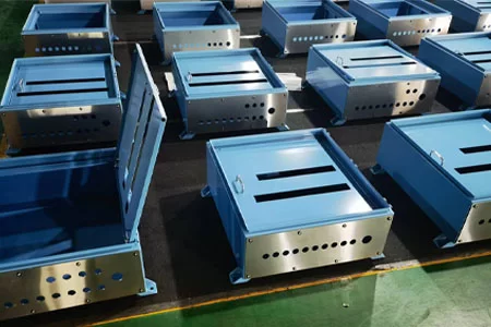
Enclosure builders, chassis and cabinet makers, HVAC contractors, and automotive and electronics suppliers all buy welded sheet metal assemblies, and each of them arrives with a different constraint: a flatness callout, a sealing requirement, a coating that cannot survive an arc, or simply a volume that has to come off a fixture. Those constraints decide the welding route long before price does.
-
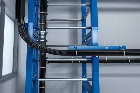
 Bridge Type Floor Stands That Hold Mesh Tray Runs Above the Floor
HULK Metal bridge type floor stands support wire mesh cable tray on a two-post frame and cross beam, with a U-shaped seat, adjustable height and finish matched to the route.
READ MORE
-
Wall Brackets That Mount a Perforated Cable Tray to a Side Wall
HULK Metal WB wall brackets mount a perforated cable tray on a side wall, with arm lengths from WB-100 to WB-700, steel, aluminum and stainless options and EG, HDG, AZM or PC finishes.
READ MORE
-
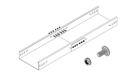
Inside Straight Coupler for Perforated Cable Tray
The HULK Metal inside straight coupler connects two perforated cable tray lengths in line, in ISC-50 to ISC-200 heights and the same grade and finish options as the tray.
READ MORE
-
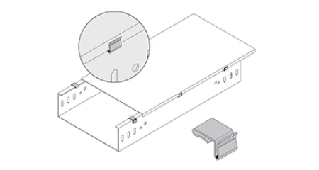
Cover Clamp 2 for Securing Cable Tray Covers
Cover Clamp 2 (CLP-CC2) secures cable tray cover panels in place, with custom heights and radii available, in the HULK Metal tray accessory range.
READ MORE
-
Cover Clamp 1 for Securing Cable Tray Covers
Cover Clamp 1 (CLP-CC1) secures cable tray cover panels in place, with custom heights and radii available, in the HULK Metal tray accessory range.
READ MORE
-
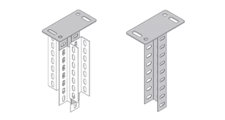
Ceiling Bracket-A with Vertical Posts for Cable Tray Support
Ceiling Bracket-A (CB A) suspends cable trays under ceilings with vertical posts and crossbar, heights 300-3000 mm, hot-dip galvanized, load tested to DIN EN IEC 61537.
READ MORE
-
Cable Tray Bolt and Nut for Ceiling Suspension
HULK Metal bolt and nut sets suspend perforated cable trays under ceilings. Four catalog codes cover M6 to M12, with matched finishes for indoor and outdoor runs.
READ MORE
-
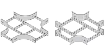
Horizontal Cross in Cable Ladder System
The horizontal cross is a crucial intersection in cable ladder networks, demanding precise geometry and robust construction. Our OEM service extends beyond simple branding: we tailor dimensions, surface finishes, and even rung spacing to your project specs.
READ MORE
-
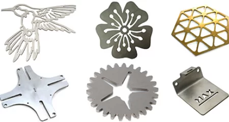
Laser Cutting Metal Parts Factory
We can develop a complete solution based on your server switch rack enclosure cabinets drawings, quantity, delivery time, transportation method and other requirements, allowing you to complete higher quality procurement tasks more easily.
READ MORE
-
OEM Server Switch Rack Enclosure Cabinet
We can develop a complete solution based on your server switch rack enclosure cabinets drawings, quantity, delivery time, transportation method and other requirements, allowing you to complete higher quality procurement tasks more easily.
READ MORE
-
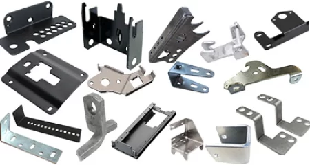
Custom Metal Brackets Factory In China
We can select the appropriate process, make molds, and complete the production of metal brackets according to your drawings, materials, tolerances, quantities and other requirements.
READ MORE
-
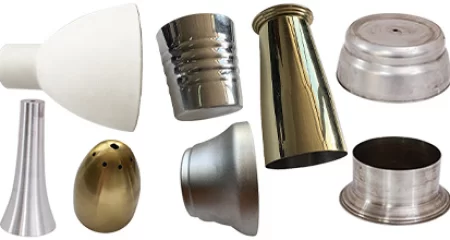
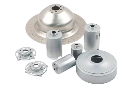
Sheet Metal Spinning Parts Factory In China
HULK Metal is committed to providing high-quality sheet metal spinning parts OEM services to customers around the world. We have an ISO 9001 certified factory and integrated supply chain.
READ MORE
-
Sheet Metal Parts Manufacturer In China
HULK Metal is a well-known sheet metal parts manufacturer in China, which provides complete solutions to produce higher quality customized sheet metal parts at lower prices.
READ MORE
-
Metal Stamping Parts Factory
HULK Metal is an ISO 9001 certified metal stamping factory that can provide you with high-quality OEM stamping services such as blanking, bending, drawing, forming, spinning, etc.
READ MORE
More Results
Sheet Metal Welding on the HULK Metal Production Floor
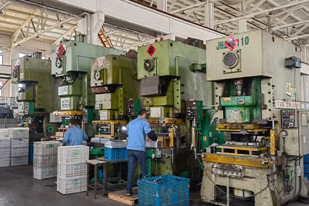
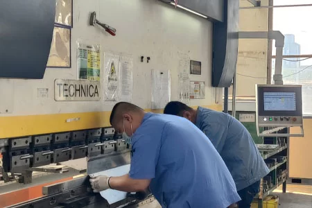
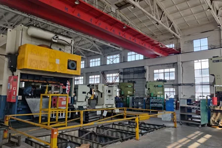
Cutting, forming, welding, surface treatment and assembly sit in one supply chain inside an ISO 9001 system, so a part is not handed between suppliers and re-fixtured between operations. Welding runs across MIG, TIG, spot and laser processes, with the inspection centre checking dimensions, hardness, coating thickness and surface quality against the requirement on the drawing.


-
![Choose a Chinese OEM for Server Rack Trays]()
March 25, 2025
Choose a Chinese OEM for Server Rack Trays
READ MORE
-
![Metal Stamping OEM Factory in China]()
March 25, 2025
Metal Stamping OEM Factory in China
READ MORE
-
![HULK Metal Fabrication]()
October 18, 2024
HULK Metal Fabrication
READ MORE
-
![Where Cables Enter and Leave a Cable Ladder System: Transitions, Bend Radius and Edge Protection]()
September 30, 2026
Where Cables Enter and Leave a Cable Ladder System: Transitions, Bend Radius and Edge Protection
READ MORE
-
![Stamping vs Fabrication: Presses, Brakes and Volumes]()
September 30, 2026
Stamping vs Fabrication: Presses, Brakes and Volumes
READ MORE
-
![Bending Sheet Metal: Radii, Springback and Tooling]()
September 29, 2026
Bending Sheet Metal: Radii, Springback and Tooling
READ MORE
-
![Cable Trunking vs Cable Tray: Protection and Access]()
September 28, 2026
Cable Trunking vs Cable Tray: Protection and Access
READ MORE
-
![Laser Cutting vs Shearing - Kerf, Speed and Edge Quality]()
September 27, 2026
Laser Cutting vs Shearing - Kerf, Speed and Edge Quality
READ MORE
-
![Designing Sheet Metal Enclosures: Ventilation, Sealing and EMC]()
September 27, 2026
Designing Sheet Metal Enclosures: Ventilation, Sealing and EMC
READ MORE
-
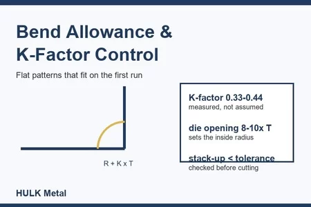
![How to Control Bend Allowance and K-Factor - A Shop-Floor Method for Sheet Metal Flat Patterns]()
September 27, 2026
How to Control Bend Allowance and K-Factor - A Shop-Floor Method for Sheet Metal Flat Patterns
READ MORE
-
![How to Spec Sheet Metal Fabrication: Materials, Tolerances, Finishes]()
September 27, 2026
How to Spec Sheet Metal Fabrication: Materials, Tolerances, Finishes
READ MORE
-
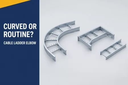
![Curved or Routine? Choosing the Right Cable Ladder Elbow for the Route]()
September 21, 2026
Curved or Routine? Choosing the Right Cable Ladder Elbow for the Route
READ MORE
-
![Cable Tray Fill Calculation: From a Cable Schedule to Width, Depth and Spare Capacity]()
September 14, 2026
Cable Tray Fill Calculation: From a Cable Schedule to Width, Depth and Spare Capacity
READ MORE
-
![Connecting New Tray to an Existing Run: Angles, Reducers and Tolerances]()
September 11, 2026
Connecting New Tray to an Existing Run: Angles, Reducers and Tolerances
READ MORE
-
![Cable Ladder Systems for Heavy Industrial Runs: How to Spec Side Rails, Rungs and Load Ratings]()
September 05, 2026
Cable Ladder Systems for Heavy Industrial Runs: How to Spec Side Rails, Rungs and Load Ratings
READ MORE
-
![Pre-Galvanized, HDG, ZAM, Stainless or Aluminum: How to Buy Cable Tray Material That Matches the Site]()
September 05, 2026
Pre-Galvanized, HDG, ZAM, Stainless or Aluminum: How to Buy Cable Tray Material That Matches the Site
READ MORE
-
![Cable Tray Installation: A Field Guide to Supports, Spacing and Bonding]()
August 19, 2026
Cable Tray Installation: A Field Guide to Supports, Spacing and Bonding
READ MORE
-
![Metal Deep Drawing: A Comprehensive Guide]()
March 24, 2025
Metal Deep Drawing: A Comprehensive Guide
READ MORE
-
![Comprehensive Guide to Sheet Metal Bending]()
March 21, 2025
Comprehensive Guide to Sheet Metal Bending
READ MORE
-
![Sheet Metal Spinning]()
March 21, 2025
Sheet Metal Spinning
READ MORE
-
![A Suitable OEM Factory for Your Network Server Blank Panels]()
February 28, 2025
A Suitable OEM Factory for Your Network Server Blank Panels
READ MORE
-
![A Comprehensive Guide to Network Server Racks]()
February 26, 2025
A Comprehensive Guide to Network Server Racks
READ MORE
-
![Comprehensive Guide to Sheet Metal Spinning]()
December 04, 2024
Comprehensive Guide to Sheet Metal Spinning
READ MORE
-
![Introduction to Sheet Metal Forming: Processes, Materials, and Choosing the Right Partner]()
October 29, 2024
Introduction to Sheet Metal Forming: Processes, Materials, and Choosing the Right Partner
READ MORE
-
![Comprehensive Guide to Sheet Metal Cutting: Methods, Materials, and Choosing the Right Partner]()
October 25, 2024
Comprehensive Guide to Sheet Metal Cutting: Methods, Materials, and Choosing the Right Partner
READ MORE
-
![Comprehensive Guide to Sheet Metal Blanking]()
October 24, 2024
Comprehensive Guide to Sheet Metal Blanking
READ MORE
-
![Comprehensive Understanding of Sheet Metal Welding]()
September 30, 2024
Comprehensive Understanding of Sheet Metal Welding
READ MORE
-
![8 Types of Sheet Metal Assembly Technology and Their Processes and Applications]()
September 27, 2024
8 Types of Sheet Metal Assembly Technology and Their Processes and Applications
READ MORE
-
![The Most Comprehensive Introduction To Metal Stamping Dies]()
September 24, 2024
The Most Comprehensive Introduction To Metal Stamping Dies
READ MORE
-
![Introduction to Metal Stamping Processes]()
September 19, 2024
Introduction to Metal Stamping Processes
READ MORE



Previous article: Sheet Metal Bending Defects: Causes, Fixes and the Pre-Shipment Checks
Next article: Stamping vs Fabrication: Presses, Brakes and Volumes
More Sheet Metal Fabrication Articles from HULK Metal
leave a message