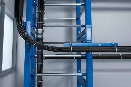
Specify a cable ladder cover by measured rail fit, panel profile, finish and separate clamp scheme. HULK Metal supports drawing-based customization and batch inspection.

A removable cover system selected by rail geometry, exposure, fixing, service access and maintenance removal.
Cable Ladder Cover Plates for Mechanical Protection and Dust Control
Industries
-
- Cable Ladder Cover Plate Fit, Joints and Service Access
- Cable Ladder Cover Plates for Mechanical Protection and Dust Control
- Left Reducer Cable Ladder Rack
- Horizontal Elbow Cable Ladder Rack Fittings
- Horizontal Tee Cable Ladder Fittings
- Middle Reducer Cable Ladder Rack
- Right Reducer Cable Ladder Rack
- Vertical External Bend Cable Ladder Fittings
- Vertical Internal Bend Cable Ladder Fittings
- Horizontal Cross in Cable Ladder System
- Straight Cable Ladder Cable Ladder Rack
-
- Vertical Tee Fitting-B Cable Trunking Fittings for Vertical Branches
- Vertical Tee Fitting-A Cable Trunking Fittings for Vertical Branches
- Vertical Internal Bend Cable Trunking Fittings for Level Changes
- Vertical External Bend Cable Trunking Fittings for Level Changes
- Vertical Cross Fitting-B Cable Trunking Fittings for Four-Way Junctions
- Vertical Cross Fitting-A Cable Trunking Fittings for Four-Way Junctions
- Upward Vertical Turning Elbow Fittings for Rising Trunking Runs
- Upper Vertical Tee-B Cable Trunking Fittings for Rising Branches
- Upper Vertical Tee-A Cable Trunking Fittings for Rising Branches
- Upper Horizontal Cross-B Cable Trunking Fittings for Four-Way Junctions
- Upper Horizontal Cross Cable Trunking Fittings for Four-Way Junctions
- Slope Turn Cable Trunking Fittings for Inclined Routes
- Right-Bottom Vertical Tee Fittings for Descending Trunking Branches
- Right-Bottom Vertical Elbow Fittings for Descending Trunking Runs
- Right Upper Vertical Tee Fittings for Rising Trunking Runs
- Right Upper Vertical Elbow Fittings for Rising Trunking Runs
- Left-Bottom Vertical Tee Fittings for Cable Trunking Drops
- Bell Mouth Fittings for Cable Trunking Entry Points
- Left-bottom Vertical Elbow
- Left Upper Vertical Tee
- Left Upper Vertical Elbow
- Horizontal Eccentric Elbow
- Bottom Horizontal Cross-b Cable Trunking Fittings
- Bottom Horizontal Cross
- Cable Trunking Right Reducer
- Middle Reducer Cable Trunking Fittings
- Left Reducer Cable Trunking Fittings
- Horizontal Tee Cable Trunking Fittings
- Horizontal Elbow Cable Trunking Fittings
- Horizontal Cross Cable Trunking Fittings
- Cable Trunking Systems in HDG, EG, ZAM and PC Finishes
-
- Cable Tray Support Systems: C-Channel Brackets, Hangers and Ceiling Supports
- 45 Degree Perforated Cable Tray Elbow for Gradual Horizontal Turns
- ZAM Coated Perforated Cable Tray for Coastal and Marine Cable Routes
- Aluminum Perforated Cable Tray for Lightweight Ventilated Routing
- Stainless Steel Perforated Cable Tray (304/316) for Corrosive and Clean Environments
- Pre-Galvanized Perforated Cable Tray Straight Sections for Control and Signal Cables
- Hot-Dip Galvanized Perforated Cable Tray Straight Sections for Outdoor Runs
- Widening Connector Plates That Join Perforated Cable Trays at Different Heights
- Wall Brackets That Mount a Perforated Cable Tray to a Side Wall
- Vertical Internal Bend Fittings for Perforated Cable Tray Level Changes
- Vertical External Bend Fittings for Perforated Cable Tray Level Changes
- Under Floor Stand for Ground-Level Cable Tray Support
- Vertical Adjust Coupler for Cable Tray Level Changes
- U Bracket Lifting Support Crossbar for Cable Tray
- Tray Carrier for Perforated Cable Tray Joints
- Threaded Rod for Ceiling Cable Tray Suspension
- Cable Tray Right Reducer for Width Changes
- Cable Tray Raise Connection Piece for Height Transitions
- Outside Straight Coupler for Perforated Cable Tray
- Middle Reducers That Narrow a Perforated Cable Tray Run Evenly
- Left Reducers That Step Down Perforated Cable Tray Widths
- Inside Straight Coupler for Perforated Cable Tray
- Horizontal Cross Fittings for Perforated Cable Tray Systems
- Horizontal Tee Fittings for Perforated Cable Tray Systems
- Hold Down Brackets That Lock Perforated Cable Trays to Their Supports
- 90° Horizontal Elbow for Perforated Cable Tray Systems
- Perforated Cable Tray Dividers for Power, Control and Signal Separation
- Cover Clamp 2 for Securing Cable Tray Covers
- Cover Clamp 1 for Securing Cable Tray Covers
- Ceiling Bracket-A with Vertical Posts for Cable Tray Support
- Ceiling Bracket with Vertical Posts for Cable Tray Support
- C Double Channel 83x41 Bracket for Heavy Cable Tray Support
- C Channel Hanging Support 83x41 for Heavy-Duty Cable Tray Suspension
- C Channel Hanging Support 41x41 for Cable Tray Suspension
- C Channel 41x41 Brackets That Carry Tray and Pipe Supports
- C Channel 41x41 for Cable Tray Support Framing
- Cable Tray Bracket Frame for Ceiling Support
- Cable Tray Bonding Jumper for Electrical Continuity
- Cable Tray Bolt and Nut for Ceiling Suspension
- Straight Perforated Cable Trays Built for Ventilation and Load
- Perforated Cable Tray Blind Ends That Close Tray Runs Cleanly
- Angle Bar Bracket for Cable Tray Support Systems
-
- Wire Mesh Cable Tray Y Junction for Angled Branch Routing
- Wire Mesh Cable Tray Straight Section
- WA-PB Wall Brackets with Upper Snap-Ons for Wire Mesh Cable Tray
- Wire Mesh Cable Tray V Connector for Raised-Floor Support
- Strengthening Bars for Wire Mesh Cable Tray Straight Joints
- HULK Metal Wire Mesh Cable Tray Standard Tee for Continuous Branch Routing
- Wire Mesh Cable Tray Spider Bracket: Flat Fixing to Wall or Floor
- Side Bottom Buckle: The Fixing Point When No Bracket Fits
- Radian Connector: The Curved Bar Behind a Wire Mesh Tray Bend
- M Shape Bars for Wire Mesh Cable Trays: Ceiling Suspension Sized by Tray Width
- L-Shaped Wall Brackets for Wire Mesh Cable Trays on Side Walls
- Hold Down Coupler for Wire Mesh Cable Tray: Wire-Matched Clamping for Risers and Supports
- Hanging Hook for Wire Mesh Cable Tray: Threaded Rod Suspension, Sized by Rod Diameter
- Hanging Brackets for Wire Mesh Cable Trays: Ceiling Suspension Sized by Load Path
- Fastlock Brackets That Lock Mesh Tray Onto C Channel Without Bolts
- Push-In Splicers That Close Mesh Tray Joints Without Bolts
- Flush Drop In Anchors for Cable Tray Ceiling Fixing
- Cross Clips That Lock 90 Degree Wire Mesh Tray Crossings
- One Clamp, Five Fittings: The KK34 Wire Mesh Coupler
- KK28 Coupler: How Two Clamp Halves Join Wire Mesh Tray Sections
- Corner Strength Bars That Reinforce Wire Mesh Tray Tees and Crosses
- Cable Guiders That Protect Wire Mesh Tray Drop-Out Points
- C Channel Brackets That Fix Wire Mesh Tray to Support Framing
- C Channel Support Framing for Wire Mesh Cable Tray Runs
- Two-Level Bridge Type Floor Stands for Wire Mesh Cable Tray
- Bridge Type Floor Stands That Hold Mesh Tray Runs Above the Floor
- Adjustable Connectors That Join Wire Mesh Cable Trays at Field-Measured Angles
- Floor Stands Sized for 100 mm Wire Mesh Cable Tray
- 90 Degree Internal Riser Fittings for Wire Mesh Cable Tray Systems
- Factory-Made 90 Degree Horizontal Bends for Wire Mesh Cable Tray
- Floor Stands That Carry 50 mm Wire Mesh Cable Tray
- Factory-Made 45 Degree External Riser Fittings for Wire Mesh Cable Tray
- 45 Degree Horizontal Bend for Wire Mesh Cable Tray
-
- Custom Wall Mount Network Rack
- Heavy Duty Network Server Cable Management
- Custom OEM Server Rack Blank Panels
- Custom Network Server Tray
- Wall Mount Network Racks
- Network Server Rack Tray Brackets
- 1U 2U 3U 4U Server Rack Blank Panels
- 18 to 47U Network Server Cabinets
- Network Server Rack Cable Management
- 18 to 47U Network Server Rack
-
- Laser Cutting Metal Parts Factory
- OEM Server Switch Rack Enclosure Cabinet
- Custom Metal Brackets Factory In China
- Carbon Steel Stamping Parts Factory in China
- Sheet Metal Spinning Parts Factory In China
- Stainless Steel Stamping Parts Factory In China
- Aluminum Stamping Parts Factory In China
- Sheet Metal Parts Manufacturer In China
- Precision Metal Stamping Parts Manufacturer
- OEM Auto Metal Stamping Parts Factory
- Stamped Steel Parts Factory
- Metal Stamping Parts Factory
- China OEM Metal Stamping Parts
-
Features
-
Capacities
-
Description
-
Factories Visit
-
Benefits
-
Related Products
-
Articles
-
Top

Cable Ladder Cover Plate Fit, Joints and Service Access
Rail-Measured Fit
The cover schedule starts from the real seating surface, outside width and side-rail height instead of one nominal ladder size.
Joints Planned With Fittings
Straight covers, bends, tees, reducers and cable exits are reviewed on one route drawing before panel lengths and clamp quantities are released.
Service Access Built In
The clamp and joint pattern identifies which panels maintenance staff can remove without disturbing unrelated sections of the route during later service.
Separate Clamp Scope
Cover panel and clamp remain explicit line items, so the quotation shows the complete fixing interface, compatible profile and required quantity.
Acceptance Before Full Install
A dry-fit sample records seating, overlap, clamp orientation and removal method before the site repeats the operation across the full route.
Inquire Now
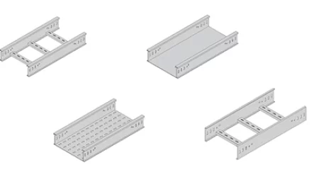
Cable Ladder System
Production Planning for Fit-Critical Cover Plates
The production release connects the rail-interface drawing, panel schedule, clamp line item and finish so the parts reach site as one traceable installation set for the approved route and its defined service method.


Clamps and Ladder Components for the Installation Set
The cover should be ordered with the ladder and clamps that define its interface. Match the rail form, clamp profile, fitting outline and finish before releasing the panel schedule, so the installation set arrives complete. These related HULK Metal pages cover the components around that measured cover schedule and the supporting route at hand, including the fittings that change the panel outline.
-
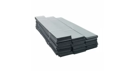
 Cable Ladder Cover Plates for Mechanical Protection and Dust Control
Specify a cable ladder cover by side-rail fit, panel edge, joint, clamp profile, material, finish and route conditions. The page separates dust and impact protection from any claim of a sealed enclosure.
READ MORE
-
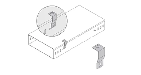
Cover Clamp 2 for Securing Cable Tray Covers
Cover Clamp 2 (CLP-CC2) secures cable tray cover panels in place, with custom heights and radii available, in the HULK Metal tray accessory range.
READ MORE
-
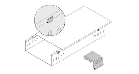
Cover Clamp 1 for Securing Cable Tray Covers
Cover Clamp 1 (CLP-CC1) secures cable tray cover panels in place, with custom heights and radii available, in the HULK Metal tray accessory range.
READ MORE
-
Straight Cable Ladder Cable Ladder Rack
The straight cable ladder is not just a simple tray section. It's the primary load-bearing element that spans between supports. Its material, dimensions, and manufacturing quality directly determine whether cables are properly supported or whether the entire system sags, corrodes, or fails inspection.
READ MORE
More Results
-
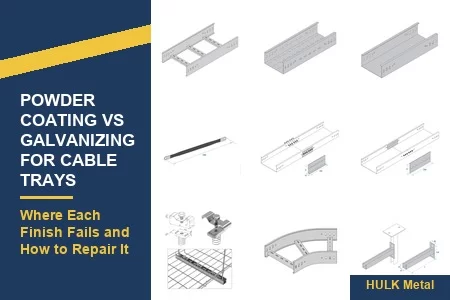
![Powder Coating vs Galvanizing for Cable Trays: Where Each Finish Fails and How to Repair It]()
October 10, 2026
Powder Coating vs Galvanizing for Cable Trays: Where Each Finish Fails and How to Repair It
READ MORE
-
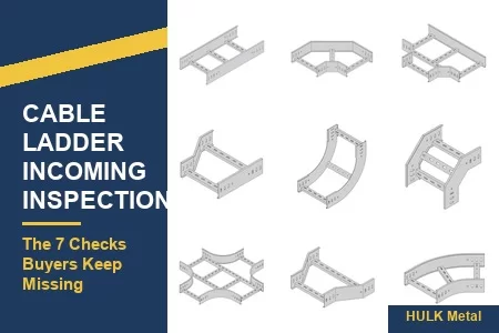
![Cable Ladder Incoming Inspection: The 7 Checks Buyers Keep Missing]()
October 08, 2026
Cable Ladder Incoming Inspection: The 7 Checks Buyers Keep Missing
READ MORE
-
![Where Cables Enter and Leave a Cable Ladder System: Transitions, Bend Radius and Edge Protection]()
September 30, 2026
Where Cables Enter and Leave a Cable Ladder System: Transitions, Bend Radius and Edge Protection
READ MORE
-
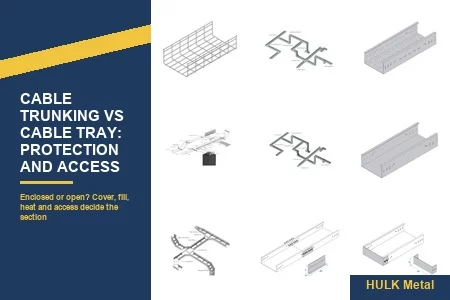
![Cable Trunking vs Cable Tray: Protection and Access]()
September 28, 2026
Cable Trunking vs Cable Tray: Protection and Access
READ MORE
-
![Cable Tray Installation: A Field Guide to Supports, Spacing and Bonding]()
August 19, 2026
Cable Tray Installation: A Field Guide to Supports, Spacing and Bonding
READ MORE