The choice of sheet metal assembly method not only affects the quality and durability of the product, but is also directly related to production efficiency and cost control. Therefore, it is crucial for designers and engineers to understand the characteri

HULK Metal is an Experienced Sheet Metal Fabricator in China
Introduce 8 Types of Sheet Metal Assembly Technology and Their Processes and Applications
-
Home>
-
Blog>
-
Technology>
8 Types of Sheet Metal Assembly Technology and Their Processes and Applications
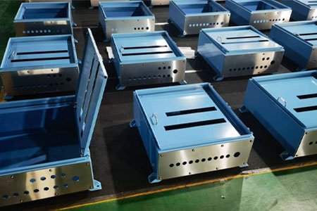 In modern manufacturing, sheet metal processing, as an important processing technology, is widely used in many fields such as machinery, electronics, and automobiles. The choice of sheet metal assembly method not only affects the quality and durability of the product, but is also directly related to production efficiency and cost control. Therefore, it is crucial for designers and engineers to understand the characteristics and applicable scenarios of various sheet metal assembly methods.
Sheet Metal Assembly methods mainly include welding, bolting, riveting, bending lap joints, flange connections, plug-in connections, threaded holes or threaded insert connections, etc. Each method has its unique advantages and applicable fields. Appropriate selection can ensure the structural strength and functionality of the product.
In the following content, we will explore these 11 sheet metal assembly methods one by one, including their working principles, advantages and disadvantages, and best application scenarios, to help you better understand how to improve the overall performance and market competitiveness of sheet metal products by choosing the right assembly method. Whether you are designing a new product or optimizing the manufacturing process of an existing product, this information will provide you with important reference and guidance.
Sheet Metal Welding:
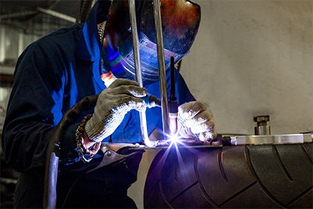
Welding is a process that forms a permanent connection by partially melting or plastically deforming separated metal or non-metal materials through heating, pressurization or a combination of both. Welding is widely used in manufacturing, construction, automotive, aerospace and other fields to produce various structures and products.
Pressure Welding:
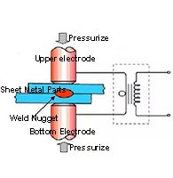
It is divided into "friction welding", "gas welding" and "resistance spot welding". "Friction welding" uses the plasticity of the material, that is, after a certain force is applied to the material and it is deformed, even if the force is no longer applied, the deformation will be maintained; "gas welding" is to press the base materials together and then heat them with gas to achieve the connection; "resistance spot welding" is to overlap the two base materials to be joined and energize them, and use resistance heating as the heat source for the connection.
In addition, "friction welding" and "resistance spot welding" and other pressure welding methods can be automated and unmanned, so automatic pressure welding machines are widely used in FA (factory automation) workshops.
Fusion Welding:
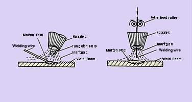
In welding, the more common method is "fusion welding".
When welding, the base material and the welding material or one of them needs to be melted to Achieve Welding.
A typical welding method is "arc welding". Arc welding and laser welding are often used for automatic welding by robots. In complex production lines such as automobile assembly lines, robot welding and manual welding are used respectively according to the characteristics and conditions of the process.
Brazing:
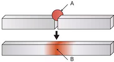
A method of joining using welding materials (braze materials) with a melting temperature (melting point) lower than that of the base material. In order to achieve joining without melting the base material and to have a good joining state with the base material, flux is added to the brazing material.
The brazing material should not only have a lower melting temperature than the base material, but also have excellent affinity, and the atoms of the molten brazing material must be able to combine with the atoms of the base material.
Brazing materials include "aluminum brazing", "silver brazing", "phosphor copper brazing", "brass brazing", etc., which can be selected according to different joining materials. In addition, "soft solder" with a low melting point such as zinc, lead, tin or tin-lead alloy is collectively referred to as "solder paste".
Brazing can easily join metals together, so it has been used in daily necessities, art crafts, and dental products for a long time. In addition, "soft soldering" of electronic circuits, etc., takes advantage of the conductivity of brazing materials and is widely used in various fields from home appliances to aircraft, nuclear industry, chemical equipment, etc.
The following is a brief introduction and comparison of resistance welding, laser welding, argon arc welding, and submerged arc welding:
Resistance Welding
Principle:
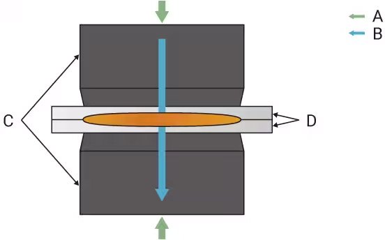
Resistance welding is a process of welding by the resistance heat generated by the current flowing through the contact points of the workpieces. Two pieces of metal are clamped by electrodes and pressure is applied. When the current passes through the contact points, heat is generated due to resistance, melting the metal at the contact points, thereby achieving welding.
Features:
No need to add welding materials.
High efficiency, high degree of automation, suitable for mass production.
Mainly used for welding thin plates, such as spot welding of automobile bodies.
Advantages:
Fast speed and high production efficiency.
High energy utilization, no need for welding fillers.
Small heat-affected zone and small deformation.
Disadvantages:
It is mainly used for thin plate materials, and the welding effect of thick materials is poor.
It requires precise control of current and pressure.
Application:
It is commonly used in welding of automobile manufacturing, home appliances, and sheet metal parts, such as spot welding in automobile body structures.
Laser Welding
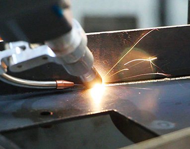
Principle:
Laser welding irradiates the workpiece with a high-energy laser beam, so that the welding area is instantly heated to a molten or vaporized state to form a welding pool. The laser can quickly heat and cool the material to form a fine weld.
Features:
The weld is narrow and the deep welding effect is good.
The energy is concentrated and the heat-affected zone is small.
It can be used for welding between different materials.
Advantages:
It has high welding accuracy and is suitable for welding of small parts and complex structures.
It is suitable for automation and remote welding.
It has fast welding speed and high efficiency, especially suitable for high-precision manufacturing industries.
Disadvantages:
It has high equipment cost and large initial investment.
It has high requirements for the surface of the workpiece before welding, and poor surface cleanliness will affect the welding quality.
Application:
Commonly used in high-tech fields such as precision manufacturing, aerospace, medical equipment, and electronic products, such as welding of electronic components and micro-mechanical parts.
TIG/GTAW Welding, Tungsten Inert Gas Welding

Principle:
Argon arc welding uses a tungsten electrode and an inert gas (such as argon) as a shielding gas to melt the metal at the high temperature generated by the arc and form a welded joint. During the welding process, the tungsten electrode does not melt, but only serves as a source of arc generation, and the welding material is usually added manually.
Features:
The high-temperature arc generated during welding is protected by argon to prevent oxygen and nitrogen in the air from contaminating the molten pool.
The weld quality is high and suitable for fine welding.
The operation is relatively slow and is usually suitable for manual operation.
Advantages:
The welding quality is high and the weld is pure, suitable for thin plates and precision welding.
It can be used for welding a variety of materials, including aluminum, magnesium, stainless steel, etc.
The heat-affected zone is small and the weld deformation is small.
Disadvantages:
The welding speed is slow and the efficiency is low.
It requires higher operating skills and is difficult to operate manually.
Application:
Commonly used in high-quality welding occasions such as aerospace, precision machinery, and automobiles, especially for welding of difficult-to-weld materials such as aluminum and titanium.
Submerged Arc Welding, SAW
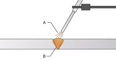
Principle:
Submerged arc welding is an automated welding process. During the welding process, the arc burns under the flux layer to form a molten pool. At the same time, the flux will melt to form a protective layer to isolate the air and prevent oxidation and pollution.
Features:
The arc is covered by the flux during the welding process, so there is no arc leakage during the welding process.
High current and high heat input are suitable for welding thick materials.
Usually automated welding with high production efficiency.
Advantages:
High welding quality, deep penetration, fast welding speed, suitable for thick materials.
No arc, less smoke, and good working environment.
The weld is well protected during welding and the welding quality is stable.
Disadvantages:
It can only be used for welding in a horizontal position, not suitable for complex welding positions.
The equipment is large and not very flexible.
Application:
Suitable for thick plate welding, such as shipbuilding, pipelines, bridges, large steel structures and other industries.
Summary Of Main Differences And Application Scenarios:
Resistance Welding:
suitable for batch welding of thin sheet metal, commonly used in automobile manufacturing, etc.
Laser Welding:
high-precision welding, suitable for high-demand fields such as electronics, aerospace, etc.
Argon Arc Welding:
suitable for high-quality welding, commonly used for thin plates, precision welding and difficult-to-weld materials such as aluminum and titanium.
Submerged Arc Welding:
suitable for thick plate welding and large-scale automated production, such as shipbuilding, steel structure and other fields.
Welding Classification Table:
Welding type | Electrical energy | Chemical energy | Mechanical energy | Light energy |
Fusion welding | Electric arc welding Electron beam welding | Gas welding | Laser welding | |
Pressure welding | Resistance welding: Resistance spot welding Projection welding Joint welding Resistance butt welding Flash welding | Explosion welding | Normal temperature crimping Friction crimping Friction stir welding Ultrasonic crimping Diffusion bonding | |
Braze welding | Induction heating welding (soft soldering) | Torch brazing (flame brazing) | Beam brazing Laser brazing |
Welding Plan:
Welding plan is a detailed plan for a specific project or product, covering welding methods, material selection, equipment, process parameters and other aspects. The following is a detailed introduction to manual welding and mechanical welding:
Manual Welding
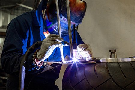
Manual welding refers to a welding method in which the operator controls the welding process manually. Usually a welding machine, welding gun and welding materials are used, which is suitable for various metal materials and different welding positions.
Advantages:
High flexibility is suitable for complex structures and difficult-to-reach welding positions.
Low Cost: Compared with automatic welding equipment, the initial investment is lower.
Easy to Operate: The technical requirements are relatively low, which is convenient for training operators.
Disadvantages:
Low Efficiency: Compared with mechanical welding, manual welding has lower production efficiency.
Unstable Quality: Due to differences in the technical level of operators, the welding quality may be inconsistent.
High Labor Intensity: Long-term manual welding can easily cause operator fatigue.
Application Areas
Maintenance and Small-scale Production: Suitable for the maintenance and customized production of small metal components.
Special Welding: Such as welding of irregular shapes or multiple materials.
Mechanical Welding
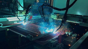
Mechanical welding refers to the process of welding by automatic or semi-automatic equipment, usually relying on machines or robots to control welding parameters and welding paths.
Advantages
High Efficiency: The speed and efficiency of mechanical welding are significantly higher than manual welding, and it is suitable for large-scale production.
Stable Welding Quality: Since the machine accurately controls the welding parameters, the welding quality is more consistent.
Low Labor Intensity: Reduces the physical labor of operators and reduces the risk of work-related injuries.
Disadvantages
High Initial Investment: The purchase and maintenance costs of automatic welding equipment are high.
Low Flexibility: Welding of complex or customized products is not as flexible as manual welding.
High Technical Requirements: Operators need to have a high level of technology and be able to debug and maintain equipment.
Application Areas
Mass Production: Suitable for industries such as automobile manufacturing and home appliance production that require a large number of repeated welding.
Precision Welding: Widely used in industries with high precision requirements such as aerospace.
Welding Plan Formulation
Material Selection
Select the appropriate welding method and welding material according to the material type of the welded product (such as carbon steel, stainless steel, aluminum alloy, etc.).
Welding Method Selection
Manual Welding: Suitable for small and complex welding work, such as repairs and customized production.
Mechanical Welding: suitable for large-scale production, high efficiency and consistency of welding must be ensured.
Equipment Selection
Select suitable welding equipment, such as manual welding machine, robotic welding system, etc., to ensure that the equipment performance meets the welding requirements.
Process Parameter Setting
Set appropriate parameters such as welding current, welding speed and heat input according to the material type and welding method.
Quality Control
Develop welding quality standards and inspection methods to ensure that the strength and appearance of the welded joint meet the design requirements.
Welding Assembly Process:
Welding assembly is a common connection method in metal manufacturing and processing. Its process usually includes preparation, welding, inspection and post-processing. The following is a detailed process of welding assembly:
Preparation Stage
Design and Planning
Engineering Drawings: Develop welding plans according to product requirements and design drawings.
Material List: List the metal materials, welding materials (such as welding rods, welding wires) and auxiliary materials required for welding.
Material Selection
Material Inspection: Ensure that the metal materials used meet the specifications and quality standards.
Material Cutting: Cut the metal materials according to the design requirements to obtain the required size and shape.
Surface Treatment
Cleaning: Remove oil, rust and oxides from the metal surface to ensure the cleanliness of the welding contact surface.
Preheating treatment (if necessary): Depending on the nature of the material, some materials may need to be preheated to reduce welding stress.
Welding Stage
Equipment Preparation
Welding Equipment Debugging: Select appropriate welding equipment (such as manual welding machine, robot welding system) and debug it.
Electrode Preparation: Select appropriate welding electrodes according to welding materials and welding methods, and ensure that the electrodes are intact.
Welding Process
Fix the Workpiece:
Use a clamp or positioner to fix the metal parts to be welded to ensure that they do not move during the welding process.
Apply Welding Parameters:
Set parameters such as welding current, welding speed, welding time, etc. according to the material type and thickness.
Start Welding:
Apply welding current and control the welding gun or electrode to weld.
During the welding process, maintain an appropriate welding speed and a stable welding posture.
Multi-pass Welding:
If multi-pass welding is required, the quality of the previous weld should be checked before each pass.
Inspection Stage
Welding Quality Inspection
Visual Inspection: Check the appearance of the weld to see if there are defects such as cracks, pores, and unwelded joints.
Dimension Measurement: Measure the size of the weld joint to ensure that it meets the design requirements.
Non-Destructive Testing
Ultrasonic Testing: Check the internal defects of the weld to ensure the quality of the weld.
X-ray Testing: Used to detect defects inside the weld, suitable for high-demand welding quality control.
Destructive Testing
Tensile Test: Stretch the weld joint to evaluate its strength and toughness.
Bending Test: Evaluate the performance of the weld under bending conditions and check its ability to resist fatigue.
Post-Processing Stage
Cooling and Cleaning
Post-weld Cooling: After welding is completed, allow the weld joint to cool naturally to avoid deformation caused by rapid cooling.
Remove Welding Slag: Clean the welding slag and oxides on the surface of the weld joint to ensure the neatness of the weld.
Surface Treatment
Rust-proof Treatment: Anti-rust treatment is performed on the welded part as needed, such as spraying anti-rust paint or hot-dip galvanizing.
Surface Polishing: If the welded part needs to be beautiful, polishing treatment can be performed.
Final Inspection And Delivery
Final Quality Inspection: Perform a comprehensive inspection of the welded assembly to ensure that all requirements and standards are met.
File Archiving: Organize relevant records and test reports during the welding process for future reference.
Delivery and Use: Deliver the welded assembly to the customer or use it for the next assembly.
Advantages & Disadvantages of Sheet Metal Welding Assembly:
Advantages
High-Strength Connection
Welded joints usually have the same or higher strength as the parent material and can withstand large loads and stresses.
Strong Adaptability
Can connect a variety of metal materials and materials of different thicknesses, with a wide range of adaptability.
Good Sealing
Welded joints have good sealing and are suitable for applications where liquid or gas leakage needs to be prevented.
Structural Integrity
Welded assembly does not introduce additional connectors like bolted connections, maintaining the integrity and beauty of the structure.
High Production Efficiency
In large-scale production, mechanical welding can greatly improve production efficiency and reduce labor costs.
Automation Is Possible
Modern welding equipment can achieve automated welding, improve production consistency and quality control.
No Heat Affected Zone During Welding
In some welding methods, the influence of heat affected zone on material properties can be reduced by controlling welding heat input.
Disadvantages
High Skill Requirements
High skill requirements for operators, especially in manual welding, improper operation may lead to welding defects.
Welding Defects
Defects such as cracks, pores, and unwelded parts may occur during welding, affecting welding quality.
Deformation Risk
The welding process may cause metal parts to deform due to local heating, affecting assembly accuracy.
Post-Weld Processing Requirements
Surface treatment, slag removal and cleaning may be required after welding, which increases the complexity of the process.
Changes In Heat Affected Zone Properties
Material properties may change in the heat affected zone, such as increased hardness or embrittlement, affecting long-term performance.
Welding Exhaust Gas And Smoke
Exhaust gas and smoke are generated during welding, which may affect the health of operators and require good ventilation and protective measures.
Applicable Parts For Welding:
Welding is a common and effective connection method in sheet metal processing, suitable for a variety of sheet metal parts. Here are some types of sheet metal parts suitable for welding:
Sheet Metal Frames
Use: Used to support and build structures such as chassis, housings or equipment brackets.
Features: Welding provides strength and stability, suitable for bearing mechanical loads.
Body Structure
Use: Car body, chassis and protective covers of cars, trucks and motorcycles.
Features: Welding can provide high strength and safety, meeting collision safety standards.
Machinery Housing
Use: Such as housings and protective covers of electrical equipment and mechanical devices.
Features: Welding has good sealing and can effectively prevent the influence of the external environment.
Ventilation And Air Conditioning System
Use: Such as ventilation ducts, air conditioning housings and vents.
Features: Good sealing performance and corrosion resistance are required, and welding can provide strong connections.
Storage Boxes And Containers
Use: Such as chemical storage tanks, oil tanks and water tanks.
Features: Welding provides good sealing and pressure resistance, suitable for storing liquids and gases.
Household Appliance Housing
Use: Such as the housings of refrigerators, washing machines, microwave ovens and other appliances.
Features: Requires beauty and durability, and the welding process can improve the appearance quality and structural strength.
Building Components
Uses: such as stair handrails, railings and metal door and window frames.
Features: Need to bear a certain load, welding provides structural stability and safety.
Sheet Metal Decorations
Uses: such as metal artworks, lamps and home decorations.
Features: Welding can achieve complex shapes and enhance aesthetics.
Transportation Accessories
Uses: such as metal parts of bicycles, motorcycles and small boats.
Features: Welding can enhance the strength and durability of components.
Structural Parts Of Elevators And Escalators
Uses: such as elevator cars, guide rails and bases.
Features: Welding provides the necessary strength to ensure the safety and stability of equipment.
Metal Storage Racks
Uses: Metal racks used for warehousing and logistics.
Features: Welding connections can ensure the stability and load-bearing capacity of the racks.
Bolt Connection:
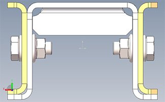
Sheet metal bolt connection is a widely used connection method for sheet metal assembly, especially in structures that need to be removable and maintainable. According to the different uses, performance and installation methods, sheet metal bolt connections can be divided into the following categories:
Ordinary Bolt Connection
Hexagonal Head Bolt:
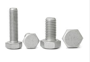
The most common type of bolt, the bolt head is hexagonal, suitable for manual or machine tool installation.
Hexagon Socket Bolt:
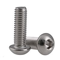
The bolt head has a hexagonal hole and needs to be installed with an hexagonal wrench. It is suitable for places with limited space.
Cross Slot Bolt:
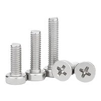
The bolt head has a cross slot and is tightened with a cross screwdriver or power tool. It is suitable for light load connections.
Self-Tapping Bolt:
Self-tapping bolts (self-tapping screws) can cut threads by themselves without pre-processing threads. This type of bolt is often used to connect thin plates.
Ordinary Self-Tapping Screws:
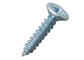
Used for thin sheet metal, the threads are cut directly on the sheet metal by rotating the bolt.
Self-Tapping Self-Drilling Screws:
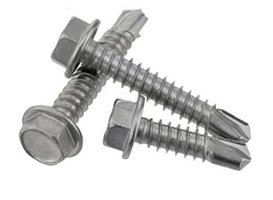
The front end of the screw has a drill bit, which can drill and tap threads by itself without pre-drilling holes, simplifying the installation steps.
Stud Connection
A stud (welding stud) is a small bolt fixed to the surface of sheet metal, suitable for occasions requiring high connection strength and vibration resistance.
Welding Stud:
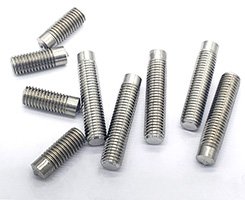
The stud is fixed to the surface of sheet metal by arc welding or resistance welding to form a permanent connection, and the nut is tightened through the stud.
Riveted Stud:
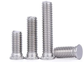
The stud is pressed into the sheet metal by mechanical pressure to fix it and form a threaded connection point.
Rivet Nut
Rivet nut is a threaded connection element suitable for thin sheets, and the threaded hole is preset on the sheet metal by riveting.
Through-Hole Rivet Nut:
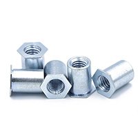
Suitable for through-hole installation, after riveting, the internal thread is formed, which is used for the detachable connection of thin sheet metal with other components.
Blind Hole Rivet Nut:
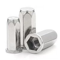
Suitable for blind hole installation, suitable for connection occasions where one side is not operable, such as in closed structures.
Cage Nut
Cage nut is a special nut installed in the hole of sheet metal, commonly used in electronic equipment chassis and sheet metal structures.
Square Card Nut:
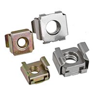
The nut is embedded in the sheet metal hole, and the nut is clamped by the spring sheet when the bolt is screwed in, which is suitable for multiple disassembly and assembly.
Spring Sheet Card Nut:
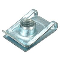
The nut is fixed in the sheet metal hole by the spring sheet, which is easy to install and has a certain shock absorption effect.
Flange Bolt
The flange bolt head has a circle of circular flange, which increases the contact area and effectively disperses the stress applied to the bolt head, which is suitable for high-strength connection.
Flat Flange Bolt:
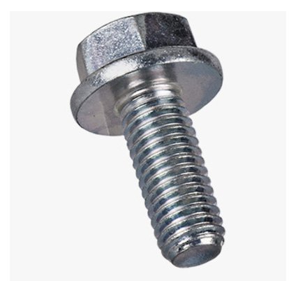
The flange is flat, which increases friction and disperses the load, reducing damage to the connecting parts.
Toothed Flange Bolt:
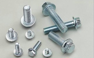
The flange surface has a toothed design, which can provide greater locking force and anti-vibration effect.
Anti-Loosening Bolt
Anti-loosening bolts are designed to prevent bolts from loosening in vibration or impact environments.
Nylon Anti-Loosening Bolt:
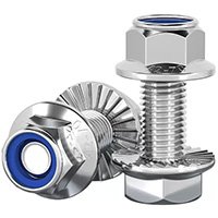
The nut has a nylon ring embedded in it, which increases friction when the bolt is screwed in to prevent loosening.
Metal Anti-Loosening Bolt:
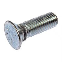
The nut or bolt has a metal locking ring or toothed design to provide additional anti-loosening force.
Stud Bolts
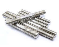
Stud bolts have threads at both ends and a smooth rod in the middle. They are often used to fix sheet metal to thick materials or large equipment.
T-bolts
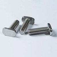
T-bolts have a "T"-shaped head and are often used in slideways, fixed brackets, and other occasions. They can be easily and quickly installed and removed.
Locking Nut Connection
Torque locking nut:
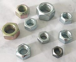
Prevents bolts from loosening through a locking mechanism. Usually the nut has a special thread shape or friction.
Slotted nut and cotter pin combination:
The nut has a slot, and the cotter pin is inserted to lock the bolt to prevent loosening. It is often used in important mechanical connection parts.
Pressure Rivet Nut
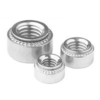
Pressure rivet nut fixes the nut in the sheet metal hole by applying pressure to form a permanent threaded connection point. It is suitable for thin sheet metal and high-strength thread requirements.
Combination Screw
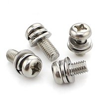
Combination screws come with washers and are suitable for occasions where quick assembly is required. By pre-assembling the screws and washers together, the installation steps are simplified.
Bolt Connection Scheme Formulation
When formulating a bolt connection scheme, design requirements, loads, environmental conditions and assembly sequence need to be considered.
Select Bolt Specifications:
Choose appropriate bolt size (diameter, length) and material according to the strength and load requirements of the connected parts.
Common bolt grades are 8.8, 10.9, 12.9, etc., and high-grade bolts have stronger bearing capacity.
Material selection: carbon steel, stainless steel, alloy steel, etc., need to be selected according to the working environment (such as high temperature, corrosion).
Determine The Tightening Method:
Use the appropriate torque value to tighten the bolts to ensure that the bolts are subjected to the appropriate preload to avoid loosening or overtightening.
Select locking washers, anti-loosening nuts, spring washers, etc. as needed to increase the stability of the connection.
Accessory Design:
In the bolt connection scheme, design a suitable hole diameter to match the bolt to ensure that the hole tolerance is reasonable to avoid loosening or instability of the bolt.
Use washers to distribute pressure and prevent damage to the connection surface.
Durability Considerations:
For connections exposed to harsh environments, consider anti-rust treatments such as electrogalvanizing, phosphating, or stainless steel bolts.
Assembly Process
Preparation:
Make sure that all connection parts (bolts, nuts, washers, etc.) are of the same size as designed and are clean.
Check the position and size of the connection holes to ensure alignment.
Component Alignment:
Align the two or more components to be connected to ensure that the bolt holes are accurately aligned. Use dowel pins or temporary fixtures to ensure that they do not shift.
Install Bolts:
Insert the bolts into the bolt holes and install all bolts in sequence to ensure that all bolts pass through the connected components.
Install Washers:
Install washers under the bolt heads and nuts to ensure even pressure distribution and avoid direct contact between the nuts and bolt heads and the component surfaces.
Tighten The Nuts:
Tighten the nuts as required with a torque wrench to ensure that the designed torque value or preload is reached to avoid over-tightening or under-tightening.
Check And Adjust:
After tightening the bolts, check whether each connection is tight and whether it needs to be adjusted again. For multi-bolt connections, it is recommended to use the diagonal tightening method to avoid deformation of components.
Anti-Loosening Measures:
If necessary, apply thread lockers on the bolt threads, or use anti-loosening devices such as anti-loosening washers or self-locking nuts.
Advantages And Disadvantages Of Bolted Connections
Advantages:
Good Disassembly:
Bolted connections can be easily disassembled and reassembled, which is convenient for maintenance and replacement of parts, and is suitable for structures that require frequent maintenance.
Wide Range Of Applications:
It can connect a variety of materials and parts of different thicknesses, such as metals, plastics, composite materials, etc., and is widely used.
Easy Installation:
Bolted connections do not require complex equipment and processes, and the installation process is simple, suitable for various working environments.
Reliable Connection Strength:
By reasonably designing bolt specifications and materials, it can ensure that the connection strength meets the design requirements and has a large load-bearing capacity.
Disadvantages:
Unstable Preload:
If not tightened correctly, the preload of the bolted connection is likely to be insufficient or excessive, affecting the stability of the connection.
Easy to loosen:
Affected by vibration, thermal expansion and contraction or other external factors, the bolts are prone to loosening and require regular inspection and maintenance.
Concentrated Stress:
Bolted connection points will produce concentrated stress, which may easily lead to local deformation or damage, especially in situations where dynamic loads are applied.
Increased Weight:
Bolts, nuts and washers will increase the total weight of the structure, especially in situations where bolts are used in large quantities.
Parts Suitable for Bolted Connection
Steel Structures:
Bolted connections are widely used in steel structures of buildings and bridges, mainly for the splicing of large components such as beams, columns, trusses, etc.
Mechanical Equipment:
Various parts of machinery and equipment, such as machine tools, heavy equipment, transmission devices, etc., are usually connected by bolts for easy installation and maintenance.
Automobile and Aviation Parts:
Bolted connections play a key role in the assembly of automobiles and aircraft, especially for parts such as engines and suspension systems, which require bolted connections to have high strength and vibration resistance.
Pipelines and Pressure Vessels:
In pipeline systems, bolted connections are often used at flange connections to ensure sealing and easy disassembly and assembly. Bolted connections are also commonly used in pressure vessels for maintenance.
Equipment Bases and Brackets:
The bases, brackets and other structural parts of large equipment are usually connected by bolts for easy adjustment and disassembly.
Riveting:
Riveting is a process of permanently connecting two or more metal sheets by applying pressure or impact force, usually without threads. Riveted connections are widely used in the assembly of sheet metal structures, especially in situations where reliable and durable connections are required but frequent disassembly is not required. The following are several common types of sheet metal riveted connections:
Solid Rivet Connection
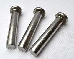
Features:
Traditional riveting method, by riveting the tail end of the rivet flat with a hammer or pressure tool to form a permanent connection.
Application:
Used for heavy-load and high-strength structural connections, such as sheet metal parts connections in large projects such as aircraft and bridges.
Advantages:
It has high shear and tensile strength.
Hollow Rivet Connection
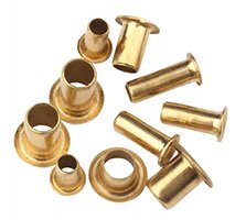
Features:
The rivet itself is hollow, and the tail end is easily deformed during riveting, and can be riveted with less force.
Application:
Commonly used in thinner sheet metal, electronic equipment and home appliances, suitable for light load connections.
Advantages:
Quick installation, suitable for thinner materials.
Semi-hollow Rivet Connection
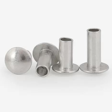
Features:
The tail end of the rivet is partially hollow, and the connection is formed by squeezing the tail end through the riveting tool. The mechanical properties are between solid and hollow rivets.
Application:
Used for structures with medium strength requirements, such as metal boxes, sheet metal shells, etc.
Advantages:
It is relatively easy to install and has good shear resistance.
Explosive Rivets
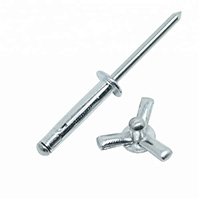
Features:
The explosion core inside the rivet expands and expands the rivet into the predetermined hole to achieve a firm connection.
Application:
Usually used in occasions where it is inconvenient to operate from both sides, especially suitable for riveting inside closed structures or pipes.
Advantages:
Single-sided operation, fast and reliable installation.
Blind Rivets
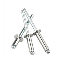
Features:
The rivet consists of a cap and a core rod. When riveting, the core rod is pulled by the tool to expand the cap and rivet the workpiece.
Application:
Widely used in industries such as automobiles, aviation, and electronic equipment, especially for connecting workpieces that cannot be touched on one side.
Advantages:
No need to operate from both sides, suitable for thin plates and limited space, and fast installation.
Closed Core-pulling Rivets
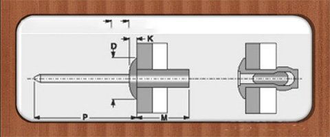
Features:
Similar to ordinary core-pulling rivets, but with a closed tail end to prevent gas or liquid penetration.
Application:
Suitable for occasions requiring sealing, such as automobile bodies and airtight containers.
Advantages:
Has a sealing effect, waterproof and dustproof.
Structural Core-pulling Rivets
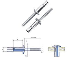
Features:
Designed for structures with higher strength, the core rod will not break during riveting, forming a stronger connection.
Application:
Commonly used in structures with higher stress, such as automobile chassis and ships.
Advantages:
High strength, excellent tensile and shear resistance.
Strike Core Rivets
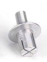
Features:
By striking the head of the rivet, the core rod is forced to expand and fix the workpiece.
Application:
Suitable for occasions that need to be operated from one side, such as light industrial manufacturing, household appliances, etc.
Advantages:
Easy installation and fast operation.
Spin Riveting (Self-piercing Riveting)
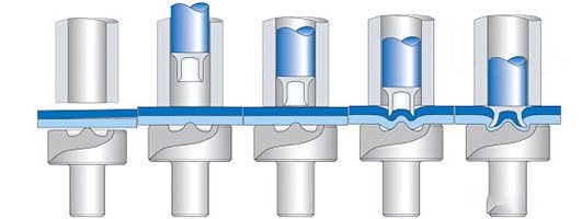
Features:
Use a rotating tool to press the rivet head into the workpiece, so that the workpiece material flows and squeezes it to fix it.
Application:
Commonly used for connections between sheet metal and aluminum, widely used in automobile manufacturing, aerospace and other fields.
Advantages:
No need for pre-drilling, high connection strength, suitable for connecting different material combinations.
Press Riveting Connection
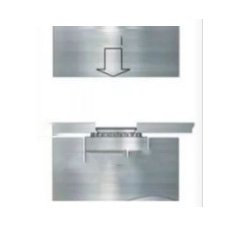
Features:
Press rivets or nuts into the sheet metal surface by pressure to form a fixed point or threaded connection.
Application:
Commonly used for fastening thin sheet metal such as electronic equipment chassis, suitable for multiple disassembly and assembly connections.
Advantages:
Easy installation and high threaded connection strength.
Blind Rivet Nut (Rivet Nut)
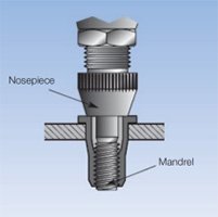
Features:
Set threaded holes on thin plates or sheet metal, install by riveting, suitable for threaded connection on the side where the nut cannot be operated.
Application:
Mostly used in thin plates and closed structures, such as automobiles, chassis, etc.
Advantages:
Suitable for thin sheet metal, provides threaded connection, suitable for structures that need to be disassembled later.
Friction Riveting
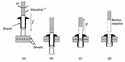
Features:
The heat generated by the friction of the high-speed rotation of the rivet softens the material, and then rivets are riveted by pressure.
Application:
Suitable for the connection of high-strength and light metals, such as sheet metal structures of aluminum alloy and magnesium alloy.
Advantages:
Strong connection, suitable for the connection of different materials.
Sheet Metal Riveting Scheme Formulation
Riveting is a common sheet metal connection method that permanently connects two or more sheet metal parts by using rivets. In order to formulate a suitable riveting scheme, multiple factors need to be considered, such as materials, connection strength, riveting environment, etc. The following is the process, advantages and disadvantages of formulating sheet metal riveting schemes, and applicable sheet metal parts.
Scheme Formulation
Requirement Analysis
Structural Requirements:
Determine the parts that need to be riveted according to the design drawings and product requirements, including connection strength and durability requirements.
Material Analysis:
Analyze the material type and thickness of the sheet metal parts to ensure that the riveting material is compatible with the sheet metal parts (such as steel, stainless steel, aluminum, etc.).
Riveting Type Selection
Solid Rivets:
Suitable for high-strength connections, such as heavy-loaded structures.
Hollow Rivets:
Used for lighter structures and have a weight-reducing effect.
Blind Rivets:
Suitable for occasions where one side can be operated, often used for thin plates.
Semi-hollow Rivets:
Provide medium strength and are suitable for medium-thick sheet metal parts.
Rivet Size and Layout
Rivet Diameter:
Determine the rivet diameter according to the sheet metal thickness and connection strength to ensure a firm connection without damaging the material.
Rivet Spacing:
Design a reasonable rivet spacing according to the stress conditions to avoid over-crowding or over-sparseness affecting the strength.
Arrangement:
Use single row, double row or matrix arrangement according to design requirements to ensure uniform force.
Riveting Tools and Equipment
Manual Riveting Tools:
Suitable for small batches and simple riveting work.
Pneumatic Riveting Tools:
Suitable for medium batch production with high efficiency.
Automatic Riveting Machines:
Used for large-scale production, which can greatly improve production efficiency and riveting quality consistency.
Riveting Process
Surface Treatment:
Before riveting, ensure that the sheet metal surface is clean and free of impurities. If necessary, pre-treatment such as degreasing and rust removal can be performed.
Alignment and Positioning:
Use a clamp or locator to accurately position the sheet metal to ensure riveting accuracy.
Rivet Installation:
Operate according to the selected riveting tool to ensure that the rivet is fully fixed and has a smooth appearance.
Inspection and Testing:
Inspect the quality of the riveting to ensure that the rivets are not loose, deformed or otherwise defective.
Advantages and Disadvantages
Advantages:
High Strength
Riveting provides a high connection strength, especially for structures subjected to mechanical loads.
High Durability
Riveting is a permanent connection method with good durability, suitable for sheet metal parts subjected to loads for a long time.
Good Vibration Resistance
Riveted connections have good vibration resistance and are suitable for connecting parts in high vibration environments.
No Complex Equipment Required
Manual or pneumatic riveting tools are relatively simple, suitable for small and medium-scale production, and easy to operate.
Suitable for Connecting Dissimilar Materials
Riveting can be used to connect sheet metal parts of different materials (such as aluminum and steel) without generating thermal stress due to the difference in materials.
Disadvantages:
Non-detachable
Riveting is a permanent connection and cannot be disassembled and reused like bolted connections.
Slower Production Speed
Riveting speed is slightly slower than welding or mechanical connections, especially in large-scale production.
Appearance Impact
Rivets produce bulges on the surface, which may affect the aesthetics of the product, especially in precision assembly or decorative structures.
Local Stress Concentration
Riveting is prone to stress concentration around the riveting points of the sheet metal, which may affect the fatigue resistance of the overall sheet metal structure.
Applicable Sheet Metal Parts
Thin-walled Sheet Metal Structures
Suitable for the use of blind rivets or hollow rivets to ensure a firm connection without damaging the material.
Automotive Sheet Metal Parts
Structural parts such as body panels, doors, and chassis often use solid or semi-hollow rivets to provide high-strength connections.
Aerospace Parts
The sheet metal skin and skeleton structure of aircraft are usually riveted to ensure strength and lightness.
Home Appliance Housings
Sheet metal housings of home appliances such as refrigerators and washing machines are quickly assembled using blind rivets.
Building Metal Structures
Applicable to various metal guardrails, stair handrails, window frames, etc. that require high-strength and durable connections.
Ventilation and Air Conditioning Ducts
Riveting is suitable for connecting metal ventilation ducts and air conditioning systems to provide airtightness and durability.
Transportation Structural Parts
The shells, frames and other parts of trains, subways and buses are riveted to withstand vibration and load.
Metal Furniture
Furniture sheet metal parts that need to be firmly connected, such as metal cabinets, tables, chairs and shelves, are often riveted.
Bending Overlap:
Sheet metal bending overlap is a common sheet metal connection process. The sheet metal plate is bent so that its edges overlap each other to form a connection. This method is usually used to enhance the connection strength, improve the protection of the seam, or prepare for subsequent welding or riveting processes. The following are several common types of sheet metal bending overlap:
Single-layer Overlap
Features:
A simple overlap method in which the edges of two sheet metal overlap each other, usually fixed by welding, riveting or screws.
Application:
Used for sheet metal connections with general strength requirements, such as light structures, boxes, etc.
Advantages:
Simple processing, suitable for light load connections, commonly used in automobile bodies, household appliances, etc.
Double-layer Overlap
Features:
Two sheets of sheet metal are bent separately to form a double-layer overlapping area, which increases the contact area and connection strength.
Application:
Suitable for occasions with higher strength requirements, often used in sheet metal structures that require durability and strength.
Advantages:
Higher strength, suitable for withstanding larger shear and tension forces.
Z-type Overlap
Features:
The edge of the sheet metal is bent multiple times to form a Z-shaped overlapping structure, which increases the strength and stability of the joint.
Application:
Used for sheet metal structures that need to enhance rigidity, such as large shells, support structures, etc.
Advantages:
It has good shear strength and deformation resistance, and can also improve the protection of the structure.
U-type Overlap
Features:
One side of the sheet metal is bent into a U shape, and the other side is inserted into the U-shaped structure to form a stable mechanical overlap.
Application:
Used in shells, pipes or other structures that need to increase protection and sealing performance.
Advantages:
Easy to install, provides good shear resistance and a certain waterproof effect.
Right-angle Overlap
Features:
Two sheets of sheet metal are bent at 90°, and the edges overlap each other to form a right angle, which is often used for the connection of frame structures.
Application:
Suitable for sheet metal structures that need to fix the edges, such as the corner connections of chassis and cabinets.
Advantages:
Provides good structural rigidity and is suitable for further processing such as welding and riveting.
Overlap Joint
Features:
Two sheets of sheet metal are completely parallel and overlapped, and can be fixed by welding, screws, etc. after bending.
Application:
Used for planar joints of sheet metal, such as the connection between the panel and the bottom plate.
Advantages:
Large overlap area, high strength, suitable for large-area planar connection.
Corner Seam Overlap
Features:
Two sheets of sheet metal are bent along the edges to form a corner seam, and the edges of the sheet metal overlap to form a stable connection structure.
Application:
Used for sheet metal splicing of corner or edge structures, such as cabinets or frame structures.
Advantages:
Enhanced connection strength of the corners, with good stability.
Locked Edge Overlap
Features:
The edges of two sheets of sheet metal are locked together by multiple bends, and no additional fasteners are required.
Application:
Used in occasions with high sealing requirements, such as ventilation ducts, roofs, containers, etc.
Advantages:
It has good waterproof and dustproof performance, and at the same time increases the connection strength.
Flanged Edge Overlap
Features:
The edge of the sheet metal on one side is bent into a flange, and the sheet metal on the other side is directly overlapped on the flange to form a simple overlap.
Application:
Used for edge protection and joint reinforcement of sheet metal, such as edge connection of chassis and door frame.
Advantages:
It can avoid exposure of sharp edges, improve safety, and enhance the durability of the structure.
Embedded Lap Joint
Features:
One side of the sheet metal is bent to form a slot, and the sheet metal on the other side is inserted into it to form an embedded connection.
Application:
Used in occasions where beautiful appearance or hidden joints are required, such as electronic equipment housing.
Advantages:
Strong connection, smooth appearance, suitable for sheet metal structures with high appearance requirements.
Curled Edge Lap Joint
Features:
The edge of the sheet metal is curled and bent to form a smooth curled edge, and another sheet metal is overlapped or embedded in the curled edge.
Application:
Used in occasions where edges need to be protected and sharp angles need to be avoided, such as the frame processing of metal plates.
Advantages:
Beautiful and safe, suitable for thin plates and applications with high appearance requirements.
Formulating a Plan For Sheet Metal Bending And Lap Joints
Sheet metal bending and lap joints are a process of connecting by bending the edge of a sheet metal and then overlapping and lap jointing it with another sheet metal part. According to design requirements and actual application scenarios, sheet metal bending and lap joints can be combined with welding, riveting or bolting to provide structural strength and stability. When formulating a sheet metal bending and lap joint plan, it is necessary to consider the thickness of the sheet metal, the bending angle, the lap length and the strength requirements of the connection.
Process of sheet metal bending and lap joints
Design and Analysis
Determine the design requirements: Review the drawings to clarify the parts, shapes, sizes and structures that need to be bent and overlapped.
Material Selection
Consider the bendability and the strength of the lap joint according to the characteristics of the material (such as steel, stainless steel, aluminum, etc.).
Determine the Bending Parameters
Bending Angle:
Commonly used angles are 90°, 45°, etc. Select the appropriate bending angle according to design requirements. 90° bending is often used to make right-angle edges, and 45° bending is used to reduce overlapping thickness.
Bending Radius:
Determine the bending radius according to the material thickness to avoid material cracking or deformation.
Overlap Length:
Determine the overlap length of the sheet metal according to the structural strength requirements. Usually the overlap length should be 3 to 5 times the material thickness to ensure the connection strength.
Bending Process
Bending Machine Settings:
According to the bending angle and sheet metal thickness, adjust the bending machine and perform a pre-bending test to ensure accuracy.
Bending Operation:
Use a bending machine or manual bending tool to bend the sheet metal to ensure that the edges are flat and the angles are accurate.
Overlap and Connection
Overlap Positioning:
Overlap the bent sheet metal with another sheet metal to ensure accurate positioning and flat overlapping surfaces.
Connection Method Selection:
Welding:
For overlaps that require high strength, spot welding, pull welding or continuous welding are often used.
Riveting:
Suitable for thinner sheet metal and occasions where welding cannot be used.
Bolted Connection:
Used for structures that are easy to disassemble or maintain.
Inspection and Adjustment
Quality Inspection:
Check the bending angle, overlap accuracy and firmness of the connection. Ensure that there are no cracks or deformations on the overlap surface.
Adjustment and Correction:
If there is a deviation in the bending or lap joint, perform a secondary bending or position adjustment.
Advantages and Disadvantages of Sheet Metal Bending and Lap Joint
Advantages:
Increase Strength:
After bending, the thickness of the lap joint increases, which can improve the mechanical strength and stability of the connection.
Simplify Processing:
Bending and lap joints can be completed through a simple bending process without complex equipment.
Strong Adaptability:
Suitable for a variety of materials, especially thin plates and medium-thick sheet metal.
Low Cost:
The processing equipment and process are relatively simple, saving production costs.
Aesthetics:
Seamless appearance connection can be achieved, suitable for products with high appearance standards.
Disadvantages:
Limited Structure:
Bending and lap joints are only suitable for simpler structures and parts that do not bear large loads.
Limited Strength:
For high-load structures, the strength of the lap joint may be insufficient, and auxiliary connection methods (such as welding) are usually required.
Processing Restrictions:
There are certain restrictions on material thickness and bending angle. Materials with too large or too small thickness may affect the bending effect.
Non-removable:
The bending and lap joints after welding are usually non-removable structures, which are not as convenient as bolt connections during maintenance.
Sheet Metal Parts Suitable for Sheet Metal Bending and Lap Joints
Case Shell
Application scenarios: such as computer cases, equipment shells, etc., bending and lap joints are often used to ensure the strength and beauty of the structure.
Home Appliance Panels
Application scenarios: such as refrigerators, washing machines and other home appliance shells, bending and lap joints can not only ensure a firm connection, but also improve the appearance quality.
Ventilation Ducts
Application scenarios: Pipes in ventilation and air-conditioning systems are often connected to pipe components by bending and lap joints to ensure air tightness.
Metal Furniture
Application scenarios: such as metal cabinets, tables and chairs, bending and lap joints are used to construct stable and beautiful furniture parts.
Light Brackets and Frames
Application scenarios: In various light brackets or frame structures, bending and lap joints can be used for simple connections, reducing the process steps of welding and bolting.
Sheet Metal Electrical Box
Application scenarios: such as distribution boxes, substation shells, etc., bending and lap joints can make sheet metal boxes more compact and sturdy.
Decorative Sheet Metal Parts
Application scenarios: used in architectural decoration, billboards and other occasions. Bending and lap joints can not only enhance the strength of parts, but also ensure the smoothness of the appearance.
Sheet metal bending and lap joints are common connection processes in sheet metal processing, suitable for the processing and assembly of various light structural parts. When formulating a plan, factors such as material properties, bending angles, and lap lengths need to be considered. A reasonable process flow can ensure the reliability and aesthetics of the connection. For sheet metal parts that bear medium loads, bending and lap joints are an economical and efficient connection method, but for structures that require higher strength or disassembly, other connection methods should be combined.
Threaded Hole or Threaded Insert Connection:
In sheet metal processing, threaded hole or threaded insert connection is a common fastening method used to ensure the detachability of components and the firmness of connections. This method is often used for thin sheet materials or sheet metal structures that require strong threaded connections. The following are several common types of sheet metal threaded hole and threaded insert connections:
Direct Tapping Threaded Hole
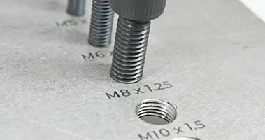
Features:
Drill holes and tap threads directly on sheet metal parts, suitable for thicker sheet metal or connections with less load.
Application:
Widely used in low-load connections, such as electrical chassis, electronic equipment housings, etc.
Advantages:
Simple process, low cost, no additional inserts required.
Pressure Riveted Nut
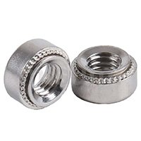
Features:
The nut is pressed into the sheet metal hole by pressure to fix it firmly and form a high-strength threaded connection point.
Application:
Used for thinner sheet metal, widely used in electronic equipment, automobiles and precision equipment.
Advantages:
Provides high-strength threaded connection, suitable for thinner sheets, easy installation, and high tensile strength.
Rivet Studs
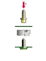
Features:
The studs are pressed into the sheet metal holes by mechanical pressure to form fixed threaded connection points, which are usually used for threaded connection between sheet metal and other parts.
Applications:
Widely used in cases such as chassis and brackets where firm fixation is required, especially where multiple disassembly and assembly are required.
Advantages:
Provides durable threads, suitable for thin sheet metal, and high strength.
Rivet Nuts
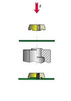
Features:
The nuts are fixed in the sheet metal by riveting, suitable for occasions where one side cannot be operated.
Applications:
Suitable for blind hole applications such as automobile and home appliance housings, especially when operation is required from one side.
Advantages:
High-strength threads can be formed on thinner sheet metals, and no operation is required from both sides during installation.
Self-tapping Screw Threaded Holes
Features:
Self-tapping screws cut threads by themselves during the screw-in process, without pre-tapping.
Applications:
Commonly used for light-load connections, such as rapid assembly of thin sheet metal parts such as household appliances and electronic equipment.
Advantages:
No need to pre-tap, simplified process steps, low cost, suitable for thin plates and soft materials.
Swage Nut
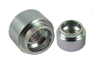
Features:
By applying pressure, the nut is expanded and firmly riveted into the sheet metal to form a permanent threaded connection point.
Application:
Commonly used in thin plate structures or occasions requiring high-strength threaded connections, such as aerospace equipment.
Advantages:
Easy to install, can provide high-strength threaded connections, suitable for thinner plates.
Locking Nut
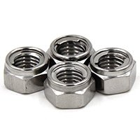
Features:
The nut is embedded with a nylon ring or adopts a special thread design, which provides additional friction to prevent loosening after tightening.
Application:
Suitable for connections that require anti-vibration and anti-loosening, such as automobiles, mechanical equipment and other occasions.
Advantages:
Provides anti-loosening effect and more reliable threaded connections.
Inlaid Thread Bushing (Helicoil Thread Bushing)
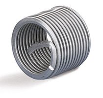
Features:
The thread bushing is a metal coil that is embedded in a pre-tapped threaded hole to provide a strong internal thread.
Application:
Used to repair damaged threads or enhance the thread strength of soft materials (such as aluminum alloys and sheet metal).
Advantages:
It can enhance thread strength, is suitable for softer materials, and prolongs the service life of threads.
Blind Hole Rivet Nut
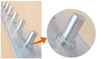
Features:
Blind hole rivet nut is suitable for sheet metal parts that can only be operated on one side. It is pressed into the sheet metal hole by mechanical pressure to form an internal thread.
Application:
Commonly used in structures where the inside of the sheet metal cannot be touched, such as closed shells, chassis, etc.
Advantages:
Suitable for single-sided operation, with high tensile strength and anti-loosening performance.
Self-drilling Screw
Features:
The front end of the screw comes with a drill bit, no pre-drilling is required, and the screw automatically drills and taps when it is screwed in.
Application:
Commonly used for light sheet metal connections, such as metal shells, building curtain walls, etc.
Advantages:
Drilling and threading are completed at one time, with simple procedures and high efficiency.
T-nut
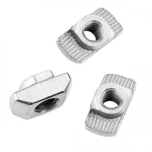
Features:
The shape of the T-nut is similar to the T-shape. When installed, it is pressed into the sheet metal hole from one side and embedded in the sheet metal through the claws on its back to form a stable threaded connection point.
Application:
Suitable for occasions with large loads, commonly seen in heavy equipment or furniture assembly.
Advantages:
Firm installation, suitable for structures that are repeatedly disassembled and used.
Cage Nut
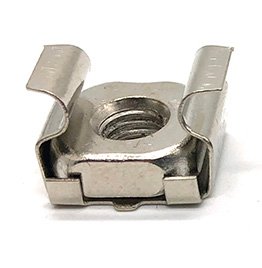
Features:
The cage nut is held by a square metal frame, and the nut can move within the frame to accommodate the position error of the bolt.
Application:
Commonly used for rack installation and electronic equipment fixing, especially when the installation space for bolts and nuts is limited.
Advantages:
Easy to install, the nut position can be adjusted quickly, suitable for occasions where it is not convenient to directly weld or fix the nut.
Scheme Formulation For Sheet Metal Threaded Hole Or Threaded Insert Connection
Sheet metal threaded hole or threaded insert connection is a common connection method, which is widely used in sheet metal parts that need to be removable and have high strength requirements. The main advantage of this connection method is that it is easy to maintain and adjust. The following will introduce the scheme formulation of this connection method in detail, including design considerations, material selection and connection requirements.
Design Considerations
Connection Strength
Choose the appropriate thread size and type (such as M3, M4, M6, etc.) according to the required load capacity and force analysis.
Determine the load capacity of each connection point to ensure that there will be no loosening or breakage in actual use.
Sheet Metal Thickness
Sheet metal thickness directly affects the processing method of threads:
For thin sheet metal (such as ≤2mm), it is recommended to use threaded inserts to increase the connection strength.
For thicker sheet metal (such as >2mm), threaded holes can be processed directly.
Material Selection
Sheet metal material: Select suitable materials according to actual needs, such as carbon steel, stainless steel, aluminum, etc.
Threaded insert material: High-strength alloy steel or stainless steel is usually used to ensure the reliability and corrosion resistance of the connection.
Threaded Hole or Insert Type Selection
Threaded Hole Processing
Direct tapping: Drilling and tapping on sheet metal, suitable for sheet metal with sufficient thickness.
Aperture design: Select the appropriate drilling diameter according to the thread specification, which is generally the ratio of the thread outer diameter (for example, M6 thread usually requires a 6.5mm hole diameter).
Threaded Insert Type
Self-tapping threaded insert: Suitable for situations where pre-tapping is not required, and it is directly installed by self-tapping, which is convenient and quick.
Compression rivet nut: The insert is fixed by a pressure riveting machine, suitable for thin sheet metal.
Hot melt insert: Suitable for plastic or soft metal sheet metal, embedded by heating or ultrasonic method.
Installation Process
Threaded Hole Processing Steps
Drilling: According to the design drawing, determine the position and drill on the sheet metal.
Tapping: Use a tapping tool to process the thread to the required depth.
Threaded Insert Installation Steps
Prepare the insert: Select a threaded insert of appropriate specifications and confirm its compatibility with the sheet metal.
Install Inserts:
Self-tapping threaded inserts: screw directly into the sheet metal hole to ensure accurate positioning.
Pressure rivet nut: align the hole position, place the pressure rivet nut in the hole, and use a pressure riveting machine to press it in and fix it.
Hot melt insert: apply hot melt adhesive to the insert and the edge of the hole, and embed it by heating.
Connection Method
Select bolts or screws: select appropriate bolts or screws according to the connection requirements to ensure that they match the threaded holes or inserts.
Tighten the bolts: tighten with a torque wrench according to the material and load requirements to ensure a firm connection.
Quality Inspection
Connection strength test: check the strength and stability of the connection through loading test or torque test.
Appearance inspection: ensure that the threaded holes and inserts are installed neatly without obvious defects or looseness.
Process of Sheet Metal Threaded Hole or Threaded Insert Connection
Requirement Analysis
Design review: analyze the sheet metal design drawings to determine the parts that need to be threaded and their structural requirements.
Material selection: select appropriate threaded hole processing or insert materials according to the thickness and hardness of the sheet metal material.
For thinner sheet metal, it is recommended to use threaded inserts to enhance the connection.
For thicker sheet metal, threaded holes can be directly processed.
Threaded Hole Processing
Drilling: Drill through holes of appropriate diameter on sheet metal according to the specifications of the thread (such as M3, M4, M6, etc.).
Tapping: Use a tapping tool to process threads in the hole. When tapping, choose the appropriate tapping depth according to the thread standard and sheet metal thickness.
If the sheet metal thickness is not enough to provide enough threads (usually at least 3 turns), it is recommended to use threaded inserts.
Threaded Insert Installation
Choose the insert type:
Choose the threaded insert type according to the material, thickness and use environment of the sheet metal, such as:
Self-tapping threaded insert: No pre-tapping is required, and it can be installed directly by self-tapping.
Compression rivet nut: The insert is fixed to the sheet metal hole by a compression riveting machine, suitable for thin plates and aluminum.
Embedded threaded insert: Embedded by hot melt or ultrasonic, usually used for plastic or softer sheet metal.
Install the Insert:
Install according to the selected threaded insert type:
Riveting method: Use a riveting machine to firmly combine the insert with the sheet metal to ensure the position and accuracy of the insert.
Hot melt or ultrasonic method: Heat or vibrate to embed the insert into the sheet metal hole, commonly used for plastic and metal joints.
Connection and Testing
Screw tightening: Install the screw into the threaded hole or insert to ensure that the screw is tightened and firmly combined.
Quality inspection: Check whether the connection is stable and whether the threaded hole or insert is installed in place without looseness or deviation.
Testing: Verify the load-bearing capacity and connection strength of the threaded hole or insert through loading test, tightening test, etc.
Advantages and Disadvantages of Sheet Metal Threaded Hole or Threaded Insert Connection
Advantages:
Removability
The threaded connection method is easy to disassemble and maintain later, especially suitable for sheet metal parts that need to be frequently disassembled or assembled.
Adapt to Thin Sheet Metal
By using threaded inserts, a firm threaded connection can be achieved on thin sheet metal, solving the problem that thin sheet materials cannot provide enough thread turns.
Enhanced Connection Strength
For structures with high strength requirements, threaded inserts can greatly improve the load-bearing capacity and wear resistance of sheet metal parts.
Multiple Thread Specifications
According to actual needs, threaded holes or inserts of different specifications can be selected to meet the requirements of bolts or screws of different sizes.
Simple Installation
Whether it is threaded hole processing or threaded insert installation, it can be completed with simple tools, with high production efficiency.
Disadvantages:
Sheet Metal Thickness Limit
For thinner sheet metal parts, direct tapping of threaded holes may result in insufficient number of thread turns, affecting the connection strength, and threaded inserts must be relied on.
Increased Insert Cost
Although threaded inserts enhance the connection strength, they increase additional material and installation costs.
Large Space Occupation
Using threaded inserts on sheet metal parts will increase the thickness of the component and affect the overall structural compactness of the component.
Limited Force
The load-bearing capacity of threaded hole or insert connection is relatively limited, and it is not suitable for parts that are subject to high impact or vibration.
Sheet Metal Parts Suitable for Sheet Metal Threaded Holes or Threaded Inserts
Electronic Equipment Housing
Application scenarios: such as computer cases, electrical control boxes, etc., which need to frequently open and close covers, use threaded holes or inserts to connect and facilitate disassembly and assembly.
Precision Mechanical Components
Application scenarios: In situations where mechanical parts and racks need to be tightly connected and disassembled, threaded inserts can ensure accuracy and strength.
Household Appliance Housing
Application scenarios: Panels such as air conditioners and refrigerators that need to be fixed with screws, the use of threaded inserts can enhance the connection strength and convenience.
Automotive Sheet Metal Parts
Application scenarios: Threaded inserts are often used in parts such as car doors and roof sunroofs that require tight connection and detachability.
Aerospace Components
Application scenarios: Sheet metal components inside aircraft, threaded inserts are used to ensure stable connection of lightweight materials.
Sheet Metal Structure of Medical Equipment
Application scenarios: Racks and panels in medical devices are often connected using threaded inserts to ensure precision and easy maintenance.
Communication Equipment Chassis
Application scenarios: Sheet metal parts that require maintainable and high-strength connections, such as base station equipment and server cabinets, often use threaded holes or inserts.
Decorative Metal Structures
Application scenarios: For example, curtain wall decorative sheet metal parts, which are connected using threaded inserts, are easy to install and maintain later.
Summary:
Sheet metal threaded hole or threaded insert connection is an efficient, convenient and flexible connection method, suitable for a variety of sheet metal parts that require detachability, precision and strength. Its advantages are easy installation and strong adaptability, especially for thin plates and complex structures. However, for high-load structures, it is necessary to reasonably select the type of threaded insert to ensure the connection strength.
Flanging Connection:
Sheet metal flanging connection is a method of processing the edge of the sheet metal hole to form a raised flange or bend along the edge to increase the contact area, improve the connection strength and facilitate the subsequent fastener installation or other connection processes. Flanging connection is often used to enhance the connection strength or aesthetics, and can avoid the safety hazards caused by sharp edges. The following are several common types of sheet metal flanging connections:
Straight Flanging
Features:
A simple straight flanging is performed on the edge of the hole to form a higher edge, which is usually used to increase the thickness of the connection so that the screws or bolts can be fixed more firmly.
Application:
Suitable for occasions such as electrical housings, chassis, electronic equipment, etc. that require higher fastener installation strength.
Advantages:
Increase the thickness around the hole, improve strength and fastening effect.
Curling Flanging
Features:
The flanging is further bent into an arc or semicircle, which is usually used for connection edges that require smooth, sharp-angle-free edges.
Application:
Suitable for occasions with safety or aesthetic requirements, such as home appliances, automotive parts, etc.
Advantages:
Avoid sharp edges, improve safety, and strengthen the rigidity of sheet metal structures.
Right-angle Flanging
Features:
The flanging of sheet metal is perpendicular to the plate surface, forming a 90-degree angle, which is usually used to enhance the rigidity of the structure or as a connecting edge for other sheet metal parts.
Application:
Suitable for frame structure and sheet metal assembly, such as edge processing of chassis and brackets.
Advantages:
Enhances the bending rigidity of the edge and is suitable for a variety of connection methods such as welding and riveting.
Z-type Flanging
Features:
The flanging forms a Z-shaped structure with multiple folds, which increases the bending strength and connection area of the sheet metal.
Application:
Used for sheet metal connections that require higher strength or complex shapes, such as automotive body parts and brackets.
Advantages:
Improves the rigidity and strength of sheet metal parts and is suitable for occasions with large loads.
Inner Roll Flanging
Features:
Curl the flanging inward so that it wraps the inner edge of the sheet metal hole, usually for aesthetic and protective purposes.
Application:
Suitable for sheet metal parts that need to protect the inner edge, such as furniture, household appliances and some shell designs.
Advantages:
Avoids sharp corners on the edge of the inner hole, improves safety and enhances aesthetics.
Reverse Flanging
Features:
The flanging faces the opposite direction of the sheet metal (back side), and is used in situations where back connection or protection is required.
Application:
Used in situations where the back structure of the sheet metal needs to be connected or fastened, such as internal support structures.
Advantages:
Increases the back connection strength, avoids excess bulges on the front side, and maintains a smooth appearance.
Double Flanging
Features:
The edge of the sheet metal is flanging twice to form a double-layer flanging structure, which further enhances the shear strength and rigidity of the sheet metal.
Application:
Used in structures that bear large loads or high stresses, such as industrial equipment, aviation and automotive fields.
Advantages:
Greatly improves the strength and durability of the structure, suitable for high-load applications.
Bevel Flanging
Features:
The flanging is at a certain angle to the sheet metal surface (usually not 90 degrees), and is used for connection requirements at special angles.
Application:
Suitable for the connection of irregularly shaped sheet metal parts, such as complex brackets or non-standard sheet metal structures.
Advantages:
Provides a flexible connection method, suitable for the assembly of various special-shaped parts.
Local Flanging
Features:
Only certain parts of the sheet metal hole are flanging to increase the local strength or connection area, while other parts remain in their original state.
Application:
Suitable for sheet metal parts that require local reinforcement without affecting the overall appearance or shape, such as light support structures or shells.
Advantages:
Save materials, reduce weight, and enhance the strength of local areas.
Embedded Flanging
Features:
Use the flanging with another sheet metal part to form an embedded structure to increase the tightness and stability of the connection.
Application:
Commonly used for the connection of sheet metal frames, shells and accessories, such as electronic equipment, automotive parts, etc.
Advantages:
Provide a more stable connection method, suitable for sheet metal structures that need to be tightly combined.
Outer Curling Flanging
Features:
The flanging curls outward to form a smooth outer edge, which is usually used to strengthen the rigidity of the edge or as a decorative edge.
Application:
Used in home appliances, car shells, architectural decorations and other occasions that require beautiful and smooth edges.
Advantages:
Improve the appearance, increase the rigidity and impact resistance of the edge.
Semi-enclosed Flange
Features:
The flange is not completely enclosed, forming a partial enclosing structure, which is used in occasions that require partial protection or light support.
Application:
Suitable for lightweight sheet metal structures, such as electrical housings, ventilation equipment, etc.
Advantages:
Provides partial support and protection while reducing overall weight.
Sheet Metal Flanging Connection Scheme Formulation
Sheet metal flanging connection is a common connection method, usually used for strengthening and sealing sheet metal parts. This connection method enhances the strength of the structure by folding the edge of the sheet metal to form an edge, and provides convenience for subsequent welding, riveting or other connections. The following is a detailed scheme formulation for sheet metal flanging connection, including design considerations, processing flow, advantages and disadvantages, and applicable sheet metal parts.
Flanging Type Selection
Flanging Angle:
Select the appropriate flanging angle according to the design requirements, common ones are 90 degrees, 45 degrees, etc.
Flanging Width:
Determine the width of the flanging, which is usually designed according to the thickness of the sheet metal and the connection requirements, generally between 10mm and 50mm.
Material Selection
Sheet Metal Material:
Select suitable sheet metal materials, such as carbon steel, stainless steel, aluminum alloy, etc., based on their strength, corrosion resistance and cost considerations.
Surface Treatment of the Flanging:
If necessary, rust-proof or spray the flanging to improve durability and aesthetics.
Sheet Metal Thickness
Determine the sheet metal thickness suitable for flanging connection, which is generally between 0.5mm and 6mm. For thinner materials, pay attention to the bending strength.
Processing Process
Design Drawings
Draw detailed sheet metal flanging connection drawings, including flanging size, bending angle and connection position, etc.
Material Preparation
Material cutting: Cut the sheet metal according to the design drawings to ensure that the cutting edges are flat.
Flanging Processing
Bending Machine Selection:
Select a suitable bending machine that is suitable for the thickness and flanging requirements of the selected material.
Flanging Operation:
Place the cut sheet metal on the bending machine to ensure that it is in the correct position.
Set the parameters of the bending machine (such as bending angle and stroke), and start the machine for flanging.
Check the size and angle after flanging to ensure that it meets the design requirements.
Connection Method
Welding:
Spot welding or TIG welding can be performed at the flanging to enhance the strength of the connection.
Riveting:
Drill holes in the flanging part and fix it with rivets, which is suitable for structures with high strength requirements.
Bolt Connection:
Use bolts to fix through the flanging holes for easy disassembly and maintenance.
Quality Inspection
Flanging Accuracy Inspection
Use calipers and angle rulers to check the size and angle of the flange to ensure that they are consistent with the design drawings.
Connection Strength Test
Perform strength tests on welded or riveted connection parts to ensure that the strength of the flange connection meets the requirements.
Appearance Inspection
Check the appearance of the flange to ensure that there are no obvious defects, deformations or burrs, and the surface treatment should be smooth.
Advantages and Disadvantages
Advantages
Increased Strength:
Flanging increases the rigidity and strength of sheet metal and can withstand greater loads.
Easy to Connect:
Flanging provides sufficient surface area for welding, riveting or bolting.
Sealing:
Flanging connection helps improve sealing performance and reduce the risk of water and gas leakage.
Disadvantages
Material Waste:
Flanging processing may result in material waste, and the size needs to be reasonably designed to reduce costs.
Processing Complexity:
Flanging processing has high requirements, and the bending angle and width need to be precisely controlled.
Extra Weight:
Flanging increases the overall weight of the component, which has a certain impact on lightweight design.
Applicable Sheet Metal Parts
Box Structure:
Applicable to various electrical boxes, housings and other structural parts.
Brackets and Frames:
Commonly used in load-bearing brackets, frames and other components to enhance overall stability.
Seals:
Applicable to components that require good sealing performance, such as sinks, airtight boxes, etc.
Sheet metal flanging connection is an efficient and reliable connection method. Through reasonable design and processing flow, it can achieve structural strengthening and improved sealing performance. The key lies in the reasonable selection of flanging angle, width, material selection and connection method to ensure that the final product meets the requirements of use. Through strict quality control, the reliability and durability of the flanging connection can be ensured, which provides convenience for subsequent use and maintenance.
Adhesive Connection:
Sheet metal adhesive connection is a technology that connects two or more metal plates together with adhesives. It is widely used in manufacturing industries such as automobiles, aerospace, electronic equipment and home appliances. Compared with traditional mechanical connections (such as welding, riveting, and bolting), adhesive connections have many advantages, including light weight, uniform stress distribution, smooth surface, and reduced damage to materials.
The following are the main features and advantages of sheet metal adhesive connection:
Advantages:
Diverse Connection Methods
Adhesives can be used to connect sheet metal parts of different materials, such as metal to metal, or metal to non-metal (such as plastic or composite materials).
It can be combined with processes such as spot welding and riveting to form a hybrid connection to further improve the strength and durability of the structure.
Weight Reduction
Compared with bolts, rivets or welding, adhesive connections do not require additional mechanical fasteners, which can greatly reduce the weight of the structure. It is particularly suitable for weight-sensitive applications such as automobiles and aerospace.
Uniform Stress Distribution
Adhesives disperse the load to the entire connection area through a uniformly distributed adhesive layer, reducing local stress concentration and reducing the risk of structural fatigue and material damage.
Shock Absorption and Noise Control
Adhesives have a certain elasticity and can absorb vibration and impact, which helps to reduce noise and increase the service life of sheet metal parts.
Corrosion Resistance
Adhesives can provide a certain degree of corrosion protection, especially when connecting different metal materials to avoid electrochemical corrosion. In addition, the adhesive layer can also block the intrusion of moisture and chemicals at the joints.
Improve Aesthetics
Since no drilling or welding points are required, sheet metal adhesive connections can maintain a smooth and beautiful surface, reducing subsequent surface treatment processes such as grinding and spraying.
Simple Process
Compared with welding or mechanical connection, the process of sheet metal adhesive connection is relatively simple and suitable for large-scale automated production. The application and curing process of adhesives can be combined with other manufacturing processes to save production time.
Typical Application Cases:
Automotive Industry:
In modern automobile manufacturing, adhesive connections are often used in the assembly of body sheet metal parts, such as doors, roofs, trunk lids, etc. Adhesives are used to reduce the number of welds, reduce vehicle weight and increase body rigidity.
Home Appliance Manufacturing:
In the assembly of metal shells in home appliances such as refrigerators and washing machines, adhesives are used to achieve seamless connections to improve product appearance and durability.
Adhesive Selection:
There are various types of adhesives used for sheet metal adhesive connections, including epoxy resin adhesive, polyurethane adhesive, acrylate adhesive and silicone adhesive. The selection of suitable adhesives depends on specific application requirements, such as ambient temperature, chemical resistance, material compatibility and connection strength.
Epoxy Resin Adhesive:
Suitable for high-strength and heat-resistant applications, widely used in aerospace and automotive manufacturing.
Polyurethane Adhesive:
It has good elasticity and impact resistance and is suitable for connection parts that require a certain degree of flexibility.
Acrylate Adhesive:
It has fast curing and excellent chemical resistance and is suitable for use in high-efficiency production environments.
Silicone Adhesive:
Mainly used in applications with high temperature resistance, UV resistance and high electrical insulation requirements.
Precautions:
Surface Treatment:
To ensure good adhesion between the adhesive and the surface of the sheet metal, surface treatment such as cleaning, degreasing, grinding or pre-priming is usually required.
Curing Time:
Different types of adhesives require different curing times and conditions (such as temperature, humidity, etc.), which should be reasonably selected according to production needs.
Environmental Impact:
The adhesive used should have good weather resistance, especially when used outdoors, the impact of ultraviolet rays, temperature changes and humidity on the adhesive layer should be considered.
Plug-in Connection:
Sheet metal plug-in connection is a method of connection by inserting the edge or part of a sheet metal into the opening or groove of another sheet metal. This connection method is often used for structures that require quick assembly, disassembly or maintenance. The following are several common types of sheet metal plug-in connections:
Slot Connection
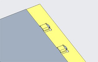
Features:
The edge of a sheet metal is inserted into the groove of another sheet metal, usually forming a certain overlap.
Application:
Widely used in structures such as chassis, housings and brackets.
Advantages:
Easy assembly, can be completed quickly without the use of tools, suitable for mass production.
Tongue and Groove Connection
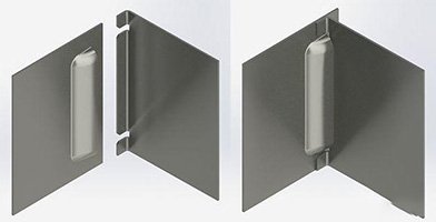
Features:
A sheet metal with a tongue is inserted into the groove of another sheet metal to form a stable connection.
Application:
Suitable for parts that require strong connections such as frames and brackets.
Advantages:
High connection strength, suitable for bearing certain tensile and shear forces.
Snap Connection
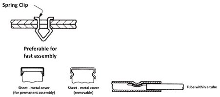
Features:
The sheet metal is designed with a protruding snap, which is inserted into the groove of another sheet metal and snapped to form a stable connection.
Application:
Used in occasions where rapid assembly is required, such as electronic equipment housings, automotive parts, etc.
Advantages:
easy disassembly, suitable for multiple assembly and disassembly, low cost.
Plug-in Connection
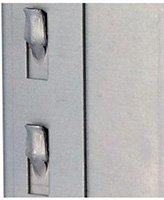
Features:
The edge or part of a sheet metal is inserted into the opening of another sheet metal, usually fixed by bending or pressing.
Application:
Used for light structures or parts that need to be frequently disassembled, such as home appliance housings.
Advantages:
It can achieve sealed connection and enhance structural stability.
Bump Connection

Features:
A boss is set on one edge of the sheet metal and inserted into the hole of another sheet metal to achieve connection.
Application:
Commonly used for the connection of light sheet metal parts.
Advantages:
Simple assembly, easy disassembly, suitable for thin sheet metal structures.
Embedded Connection
Features:
The edge of a sheet metal is embedded in the groove of another sheet metal, usually forming a mutually nested structure.
Application:
Suitable for structures that need to protect the edges, such as chassis, housings and assemblies.
Advantages:
Improves the stability and bending resistance of the connection and avoids sharp angles.
Butt-joint Connection

Features:
Two sheets of sheet metal are in parallel contact and connected by insertion.
Application:
Used for the assembly of frames and large structures.
Advantages:
Able to withstand large forces and suitable for the connection of heavy structures.
Twist-and-lock Connection
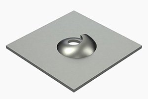
Features:
By bending the edge of the sheet metal into a spiral shape and inserting it into the hole in the other sheet metal, a fastened connection is formed.
Application:
Used for structures that require tensile and torsion resistance, such as chassis and brackets.
Advantages:
Enhances the firmness of the connection and is suitable for connection occasions with higher requirements.
Scheme Formulation of Sheet Metal Plug-in Connection
Sheet metal plug-in connection is a common sheet metal connection method, which mainly achieves a firm connection by inserting a specific part of a sheet metal part into another sheet metal part. This method is often used in structures such as casings and brackets, and has the advantages of simple structure and easy assembly. The following is a detailed scheme formulation of sheet metal plug-in connection, including design considerations, processing flow, advantages and disadvantages, and applicable sheet metal parts.
Plug-in Method
Plug-in shape: Determine the shape of the plug-in according to design requirements, such as straight plug-in, oblique plug-in or round plug-in.
Plug-in length: Determine the length of the plug-in part to ensure the stability and strength of the connection.
Material Selection
Sheet metal material: Select suitable sheet metal materials (such as carbon steel, stainless steel, aluminum alloy, etc.) based on factors such as strength, corrosion resistance and processing cost.
Surface treatment: If necessary, rust-proof or spray the surface of the sheet metal to improve durability and aesthetics.
Sheet Metal Thickness
Determine the appropriate sheet metal thickness, generally between 0.5mm and 6mm, and the thickness must meet the plug-in strength and structural requirements.
Processing process
Design Drawings
Draw detailed sheet metal plug-in connection drawings, including the size, shape and connection position of the plug-in parts.
Material Preparation
Material cutting: Cut the sheet metal according to the design drawings to ensure that the cutting edges are smooth.
Plug-in Parts Processing
Processing plug-in slots: Process the plug-in slots on the sheet metal according to the design requirements, using laser cutting or stamping methods to ensure the accuracy and smoothness of the slots.
Edge processing: Chamfer or deburr the edges of the plug-in parts to facilitate plug-in and avoid scratches.
Connection Method
Plug-in Operation:
Insert the plug-in part of one sheet metal into the plug-in slot of another sheet metal to ensure that it is plugged in place.
Fixing Method:
Welding:
Spot weld the plug-in to enhance the stability of the connection.
Bolt connection:
Drill holes in the plug-in part and fix it with bolts, which is suitable for situations where disassembly and maintenance are required.
Riveting:
Use rivets to fix at the plug-in, which is suitable for connections with high strength requirements.
Quality Inspection
Plug-in Accuracy Inspection
Use calipers and gauges to check the size and position of the plug-in to ensure that it meets the requirements of the design drawings.
Connection Strength Test
Perform strength tests on welded or riveted connection parts to ensure that the strength of the plug-in connection meets the requirements.
Appearance Inspection
Check the appearance of the plug-in to ensure that there are no obvious defects, deformations or burrs, and the surface treatment should be smooth.
Advantages and Disadvantages
Advantages
Simplicity: The plug-in connection has a simple structural design and is easy to assemble and disassemble.
Low cost: Compared with welding or riveting, the plug-in method usually has a lower processing cost.
Easy maintenance: The plug-in structure is convenient for later maintenance and replacement.
Disadvantages
Strength limitation: Compared with welding connections, the strength of plug-in connections may be lower and is not suitable for withstanding excessive impact and loads.
Uneven force distribution: The force at the plug-in may be uneven, and reasonable design is required to avoid local overload.
Applicable Sheet Metal Parts
Casing structure: Applicable to the housing of electronic products, equipment chassis, etc.
Brackets and frames: Commonly used in brackets, frame structures, etc. to enhance overall stability.
Guide rails and connectors: Suitable for guide rails, connecting brackets and other components to achieve flexible assembly.
Sheet metal plug-in connection is an efficient and flexible connection method. Through reasonable design and processing process, it can achieve a stable connection of sheet metal parts. The key lies in the reasonable selection of plug-in method, material selection and connection method to ensure that the final product meets the use requirements. Strict quality control can ensure the reliability and durability of the plug-in connection, and provide convenience for subsequent use and maintenance.
Summary:
Sheet metal assembly methods are diverse, and various methods meet different structural requirements according to their characteristics and applicable scenarios. Choosing the right assembly method requires considering factors such as material properties, connection strength, processing difficulty and post-maintenance. In modern manufacturing, the rational use of these assembly methods can effectively improve product quality and performance.
Choose HULK Metal to produce your order
Choosing HULK Metal as your sheet metal processing and production partner
will bring you many advantages. Here are some reasons to choose us:
High Quality Standards
HULK Metal uses advanced production equipment and a strict quality control system to ensure that every product meets international standards and customer requirements.
Our materials are carefully selected to ensure their strength and durability, and to ensure the reliability of the products in various application scenarios.
Diverse Processing Services
Provide comprehensive sheet metal processing services, including welding, bending, stamping, cutting, etc., to meet the needs of different customers.
With rich processing experience, we can handle various complex design and size requirements.
Professional Design Team
Our professional design team can provide personalized design solutions according to the specific needs of customers, from the initial concept to the final product, ensuring that every detail is perfect.
Supports design tools such as CAD and 3D modeling to help customers better visualize the final product.
Flexible Production Capacity
HULK Metal has flexible production capacity and can handle small and large batch orders and respond quickly to market needs.
We can provide efficient production and delivery services according to customer time requirements to ensure timely meeting of market needs.
Environmentally Friendly Production
We attach importance to sustainable development, use environmentally friendly materials and production processes, and strive to reduce the environmental impact during the production process.
HULK Metal is committed to promoting green manufacturing and meeting the requirements of modern society for environmental protection.
Excellent Customer Service
Provide a full range of customer support, including pre-sales consultation, after-sales service and technical support, to ensure that customers have no worries throughout the cooperation process.
Our customer service team is on call at any time to respond quickly to customer inquiries and needs.
Competitive Price
HULK Metal provides competitive prices by optimizing production processes and material procurement to ensure that customers get the best price-performance ratio.
No matter the size of the order, we are committed to providing reasonable quotations and transparent cost structures.
Choosing HULK Metal to produce your order is not only choosing a high-quality product, but also choosing a trustworthy partner. No matter what your project needs are, we will serve you wholeheartedly to ensure that every order of yours is delivered on time and achieves your expected results. Let us work together to move your project forward!
Article Navigation
Article Navigation
Industries
Foundries


