

Industrial cable tray management links route zones, tray geometry, support charts, fittings, segregation, finish and inspection evidence in one controlled package.

A route-package method for industrial plant engineers
Industrial Cable Tray Management: Route, Supports and Segregation
-
Home>
-
Blog>
-
Technology>
Industrial Cable Tray Management: Route, Supports and Segregation
20
2026.11
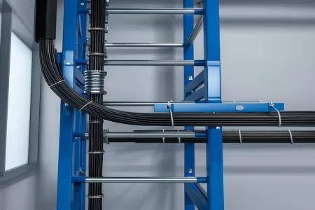
An industrial cable tray should be bought as a route package, not as a pile of straight sections. The package must connect route zones, tray geometry, supports, fittings, separation and inspection records before anyone releases the drawing.
The costliest mistake usually appears long before installation. One person prices tray metres, another chooses brackets, a third adds dividers, and the site team discovers the missing interfaces only when the route is already being installed. This guide sets out a decision sequence for an industrial cable tray system that an OEM, EPC contractor or plant buyer can quote and verify as one controlled package.
Core rule: if the tray, support, separation or handover information is missing, the route is not ready for a comparable quotation. Keep the missing item open instead of hiding it inside a nominal price per metre.
✓ Define the route by operating zones, not by one plant-wide tray description.
✓ Recalculate the applicable load chart whenever the tray section or support span changes.
✓ Assign the owner of supports, fittings, dividers, covers and bonding accessories.
✓ Release production from a drawing, component schedule and inspection plan that use the same identifiers.
Start With Route Zones, Not Tray Metres
A route zone is a portion of the cable system with the same operating duty, environment, access condition and acceptance logic. Treating it as a procurement unit is more useful than dividing the plant only by drawing sheet number.
A process bay, an electrical room, an outdoor pipe bridge and a future expansion corridor rarely need identical tray geometry or finish. They may also have different owners and different inspection windows. Once those differences are exposed, the buyer can compare quotations without guessing which scope was included.
For an initial review, compare a cable schedule with the plant layout and mark four breaks: environment, cable duty, support structure and maintenance access. A change in any one of them is a reason to test whether the route should become a separate package. A change in all four almost always should.
Process area: start from cable weight, ambient conditions, hot surfaces, washdown and the structure that can carry the supports.
Confirm whether the route is open ladder, perforated tray or enclosed trunking; whether covers and dividers are needed; and whether field cuts will require a defined finish-repair method.
Service corridor: the controlling issue is often access and coordination with other trades, not the tray alone.
Capture support locations, lifting points, maintenance clearance, cable pulling direction and the sequence for installing fittings where several disciplines share the corridor.
Future tie-in: a route that may be extended needs an interface strategy, not merely extra tray length.
Define spare capacity, available branch fittings, divider continuity, support capacity and the approval route for later changes. Any project-specific reserve or fill limit must come from the responsible specification.
Table 1. Inputs that should be fixed before a route zone is quoted.
| Decision | Record to close | Why it changes the package |
|---|---|---|
| Route boundary | Zone start, end and interface | Prevents gaps between drawing packages |
| Cable duty | Cable schedule and separation requirement | Changes width, divider and cover selections |
| Structure | Support type and fixing interface | Changes span, bracket and installation details |
| Environment | Exposure and finish | Changes material, coating and repair rules |
Build a Route Hierarchy That Can Survive Detail Design
A practical hierarchy moves from plant demand to route corridor, then to tray section, support and local interface. If the order is reversed and a preferred tray is chosen first, later cable or structure constraints force expensive changes.
Begin with cable groups and destinations. Grouping every cable into one trunk creates a large route with difficult branch control; separating every circuit creates a crowded support field. The useful middle ground is a route hierarchy that follows process units, electrical rooms and major cable duties. The project engineer owns that split; the tray supplier turns the agreed split into product, fitting and accessory packages.
The hierarchy should be visible on the drawing itself. A colour, line type or table can identify the system, zone and package reference. That simple convention prevents a production query from turning into an uncontrolled verbal change.
Step 1: Plant demand
Map major cable groups, source equipment, destination equipment and expected future branches.
Step 2: Route corridor
Choose the physical corridor and record which structure owns the supports at each interface.
Step 3: Tray geometry
Select width, height, thickness and product family against the cable schedule and environment.
Step 4: Interfaces
Close splices, bends, dividers, bonding, supports and transitions with dimensions and component identity.
Match Tray Geometry to the Duty, Not to a Familiar Size
Width and height are often copied from a previous project because they look familiar. In an industrial route, the correct starting point is the cable schedule, the installation rules and the load chart for the exact tray construction.
The approved HULK Metal company fact sheet confirms custom widths from 50 to 1200 mm, heights from 10 to 200 mm and material thicknesses from 0.5 to 3.0 mm. Those figures define the manufacturing envelope. They do not mean every combination shares one load rating or one support spacing.
For the drawing, state nominal width, side height, thickness, material and finish together. Add the cable fill or cable schedule reference, allowed bend radius and any divider position. If a field condition is not known, name the party who will confirm it and set the release hold point.
50-1200 mm
Width
Confirm cable capacity, divider space and fitting geometry.
10-200 mm
Height
Confirm cable stack, cover clearance and connection depth.
0.5-3.0 mm
Thickness
Use the applicable load chart, not an assumed material equivalence.
±0.05 mm
Raw-material tolerance
Keep the source inspection record with the batch.
±2 mm
Finished size tolerance
Apply it to the confirmed product-size requirement.
Project-specific
Load chart
Select the row for the tray, span and deflection basis.
Table 2. Released geometry must use one basis across drawing, offer and inspection.
| Field | Good release value | Bad release value |
|---|---|---|
| Tray | HM-Q-P-01A-30050-E40 | 300 perforated tray |
| Span | Support spacing and load-chart reference | Standard spacing |
| Finish | E40, H45 or approved project finish | Galvanized |
| Accessory | Coupler, divider and bracket code | All fittings included |
The code-guide example is useful because it compresses product identity into a reusable string. It is only reliable when the quotation, packing list and inspection record use the same interpretation. A short written description cannot carry the same control if the project contains similar trays with different heights or finishes.
Design the Support Interface With the Tray
A tray catalogue answers what the tray can carry under a stated test condition; it does not choose the building anchor or certify the supporting structure. The support interface should therefore be released together with the tray schedule.
HULK's catalogue load charts are tested according to DIN EN IEC 61537. The practical consequence is straightforward: find the chart row for the actual tray and span, then check whether the support scheme produces that condition. Do not transfer a value from a narrower, thicker or differently supported tray simply because the outside dimensions look similar.
Support planning should identify the ordinary intermediate supports, end conditions, junctions where fittings change the load path and locations where another trade may add equipment later. It should also show which bracket family is used: Ceiling Bracket, wall bracket, channel support, hanging support or another approved detail.
▸ Match the support type to the actual structure and load path.
▸ Keep the tray chart, span and bracket detail under one package reference.
▸ Flag anchor design and structural adequacy as project-engineer scope.
▸ Reopen the check if the tray, span, fitting layout or accessory load changes.
The factory can inspect the bracket geometry, material and finish against the approved drawing, but the site structure remains a separate design responsibility. Keeping that boundary explicit prevents a common quotation error: assuming that a tray load table also confirms the anchor capacity of a concrete beam or steel purlin.
Use Fittings to Protect Geometry and Cable Radius
A straight run becomes a system only when every change of direction, width and elevation is resolved. Fittings should be selected from the agreed tray family and checked against the cable bend radius, available space and support positions.
Horizontal elbows, vertical bends, tees, crosses, reducers, widening connectors, couplers and end closures each change how the route is assembled. The drawing should show the angle, width and height at both sides of a fitting. For a tee or reducer, "make it fit on site" is not enough because the factory cannot release a controlled component from that instruction.
Joints need the same attention as bends. A coupler does not stop needing support just because it is a small component. When a joint sits near a support, a bend or a branch, the inspection should confirm that the plates engage correctly and that the cable path remains smooth. The approved Cable Tray Installation checks should be applied at the installed condition, not only at the factory.
Hold point: if a dimension is marked "field measure", define who supplies the measurement, when production may start, and whether Adjustable Connectors or another special component will absorb the difference.
Assign Segregation and Bonding Before Pricing
Power, control, instrumentation and communication cables do not become separated simply because they are placed in the same wide tray. The design has to say whether separation is by distance, divider, enclosed section or another project-approved arrangement.
The purchase package should list dividers by location, cover type by zone and bonding accessories by joint or interface. Where steel tray provides part of the electrical path, the project team must state the required continuity check and where it is performed. HULK can supply listed bonding-jumper and divider components; the electrical acceptance rule remains a project document.
Mixed materials need explicit treatment as well. A stainless tray, galvanized support and another fixing material may require an isolating or compatible detail to avoid an unintended contact condition. The route drawing should identify the transition and the responsible component, not leave the choice to an installer's general practice.
Table 3. Separation decisions that must have a physical owner.
| Interface | Question to close | Package evidence |
|---|---|---|
| Power / signal | Which rule controls separation in this zone? | Zone note and divider schedule |
| Steel continuity | Where must the bonding path be verified? | Joint schedule and test hold point |
| Dissimilar metals | Which surfaces may not touch directly? | Transition detail and fixing material |
| Covers | Is the cover for protection, access or another duty? | Cover type and opening/access route |
Make Finish and Environment Part of the Same Package
The finish is not a colour note added at the end of the drawing. It controls which material and processing route can be quoted and how cut edges, field holes and transport damage will be handled.
The approved product range includes pre-galvanized, hot-dip galvanized, stainless and aluminum options in the Cable Tray System catalogue. Each family has different handling and repair considerations. The correct choice depends on the actual exposure, expected cleaning, contact with other materials and the project's acceptance method. Narrow the application context before selecting the finish, then state the finish class and any field-repair requirement in the package.
"Galvanized" by itself is not a release value. The product code and drawing should identify the intended finish class, and the quote should state whether field cuts need a specific repair product. If the environment is outside the company's confirmed evidence boundary, record it as a technical query rather than converting a generic coating description into a guarantee.
External exposure is a package decision: tray, covers, supports, fasteners and repair method must be compatible. A selected tray finish paired with unprotected field-cut edges or mismatched supports does not produce a coherent system.
Turn the Drawing Into a Controlled Release Package
Production should not begin from "latest drawing" alone. It should begin from a released package with a fixed revision, component schedule, quantity basis and acceptance plan.
The package can remain compact for a simple route, but it needs the same logic at every scale. The route drawing shows location and interfaces. The component schedule lists tray, fittings, covers, dividers, couplers and bonding items. The inspection plan states what will be checked at first article, goods-in or final release.
Use identical identifiers everywhere. If the drawing says section A, the offer uses position 12 and the packing list uses a different name, receiving inspection becomes an exercise in translation. The product-code schedule is useful here because material, product form, size and finish can be checked without interpreting an abbreviation.
Drawing set
Route plan, elevations, section details, interface details and revision status.
Bill of materials
Straight sections and fittings by product code, quantity and zone.
Interface register
Supports, anchors, separations, covers and field-fit holds.
Inspection record
Characteristic, method, sample stage and release decision.
Table 4. Release test for an industrial route package.
| Check | Pass condition |
|---|---|
| Identity | Every component has a drawing position and product code. |
| Geometry | Width, height, thickness, angle and interfaces are dimensioned. |
| Load | The selected tray and span point to an applicable load-chart row. |
| Separation | Divider, distance, cover or other separation detail has an owner. |
| Acceptance | Inspection stage and characteristic are known before production. |
Inspect the Route at Three Moments
A single final inspection hides too much. The useful sequence is first article, goods-in and post-installation. Each answers a different question.
First article proves that the approved drawing has been translated into the correct geometry, material, finish and component set. Goods-in confirms that the package received matches the released schedule and that transit has not damaged the protected surfaces. Post-installation checks whether supports, joints, fittings, separators and bonding have been assembled into the intended system.
For the factory record, HULK's documented QC sequence starts with raw-material verification, continues with production inspection and ends with finished-product checks covering dimensions, performance and other drawing requirements. The buyer's inspection plan should use those stages as a starting point and add the project-specific route characteristics.
Do not double-count evidence: a certificate, a dimensional record and an installed-route inspection prove different things. A supplier cannot substitute a generic certificate for the route's support, separation and assembled-continuity checks.
What to Put in the RFQ
A useful RFQ lets the supplier quote the same object that the site will install. It does not need to be enormous; it needs to close the variables that change price, tooling, fit or acceptance.
Send zone drawings, cable schedule or design duty, tray product code, material and finish, support detail, fitting schedule and required inspection records. State whether the scope includes covers, dividers, bonding jumpers and loose fasteners. Add the commercial boundary for field measurement, repair material and spare parts.
→ Split the route into zones and attach one drawing set per zone.
→ Provide the cable duty and all known separation requirements.
→ Fix tray and support interfaces with dimensions and product codes.
→ Name the inspection stages, records and release authority.
Make the next quotation comparable
Send HULK Metal the route drawings, cable duty, support details, finish requirement and inspection plan. We will return a component-based route package with open technical boundaries instead of a price per metre that hides the interfaces.
Control Changes After the First Package Is Issued
An industrial route evolves while other disciplines finish their layouts. The objective is not to freeze every drawing early; it is to make each change land in the right package without silently invalidating earlier choices.
A new cable group can affect tray width, cover clearance, divider position, support load and fitting size. A moved steel beam can alter support type or span. A changed cleaning regime can alter the finish and field-repair method. In each case, identify the changed input first, then trace the affected outputs instead of editing only the drawing note that happens to be visible.
Use a small change log attached to the route package. Record the affected zone, reason, superseded component, replacement component and release status. This is more useful than a general revision cloud because it tells purchasing which line items changed and tells inspection which characteristics need a new first-article check.
- ■ A cable-schedule change triggers a width, fill, divider and fitting review.
- ■ A structure change triggers support detail, span and bracket review.
- ■ A finish change triggers material compatibility and field-repair review.
- ■ A fitting change triggers angle, width, height and cable-radius review.
The same discipline applies to site questions. A message such as "the route needs to move 200 mm" should return the zone, affected support references and the batch or release state. If production has already started, the buyer needs a clear decision: adapt the installed interface, remake the component or obtain engineering acceptance. Leaving that choice informal creates a traceability gap that a final inspection cannot repair.
A change-controlled route also protects the supplier's own scope. HULK can build to the approved drawing and quality plan; it cannot infer that a new beam, cable duty or electrical requirement has superseded the released values. Written revision status gives both sides a defensible boundary.
Frequently Asked Questions
Is an industrial cable tray just a larger cable tray?
No. It is one part of a route package that also needs supports, separation, access, finish and records.
Can I use one support spacing for the whole plant?
Only when the tray construction, support arrangement, span and load condition stay the same. That is rarely true across an entire plant. A heavier cable group, a different bracket family, a wider tray or a longer span can change which load-chart row applies. Releasing one spacing for every zone transfers the check to installation, where the original design inputs are harder to reconstruct.
Does HULK provide the structural anchor design?
Not by default. Anchor selection and structural adequacy belong to the responsible project engineer unless a separate scope is approved.
How should power and signal cables be separated?
Start with the project's electrical requirement, then choose a physical method: distance, divider, enclosure, cover or another approved detail. A note that says “separate power and signal” is not enough for purchasing because nobody can identify the required accessory. The drawing needs a zone, a part and an owner.
Can dimensions be checked against the drawing?
Yes. The approved drawing, product code and inspection plan should define the dimension, method and acceptance stage. The approved HULK Metal company fact sheet gives a finished-size tolerance of ±2 mm; any tighter or different project requirement must be stated and agreed separately. Keep measured records linked to the released revision so an old first article is not reused after a geometry change.
What documents should accompany the offer?
Drawing revision, bill of materials, product codes, finish, accessories, quantities, inspection plan and open questions.
How do I handle a field-measured transition?
Never release a blank dimension. Assign the measurement, deadline, approval and component.
A controlled industrial cable tray package is not more paperwork for its own sake. It is the shortest route between a cable plan and a route that can be built, inspected and changed without arguments over what was included.
Industries HULK Metal Serves for Industrial Cable Routes
HULK Metal supports industrial cable routes across manufacturing, utilities, power distribution and infrastructure projects. The route package can include tray sections, elbows, tees, reducers, couplers, covers, dividers, bonding accessories and support brackets. Project drawings and product codes keep geometry, material, finish, quantities and inspection aligned before production, so buyers can compare the complete scope rather than tray metres alone and clarify every interface before approval.
More Results
Sheet Metal Factory Support for Industrial Cable Trays
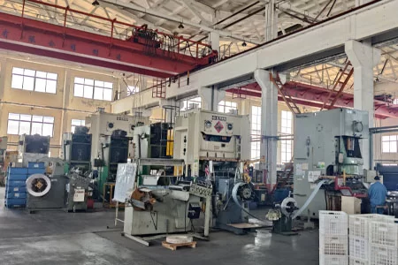
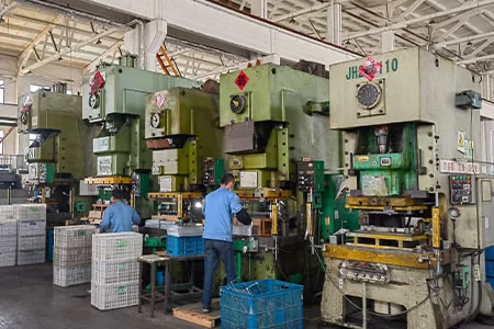
Our sheet metal workflow connects drawing review, cutting, forming, welding, surface treatment and inspection. For cable-tray projects, the released package keeps product code, geometry, finish and batch records aligned so production and receiving inspection work from the same specification. This supports controlled first-article approval, consistent handover of tray, fittings and accessories, and a clear point for resolving drawing queries before the batch is released.


-
![Choose a Chinese OEM for Server Rack Trays]()
March 25, 2025
Choose a Chinese OEM for Server Rack Trays
READ MORE
-
![Metal Stamping OEM Factory in China]()
March 25, 2025
Metal Stamping OEM Factory in China
READ MORE
-
![HULK Metal Stamping Factory Show]()
November 21, 2024
HULK Metal Stamping Factory Show
READ MORE
-
![HULK Metal Fabrication]()
October 18, 2024
HULK Metal Fabrication
READ MORE
-
![Cable Tray Installation: A Field Guide to Supports, Spacing and Bonding]()
August 19, 2026
Cable Tray Installation: A Field Guide to Supports, Spacing and Bonding
READ MORE


Previous article: None
Next article: Fire Rated Cable Tray: Coatings, Barriers and Evidence Buyers Need
More Industrial Cable Management Guidance
leave a message